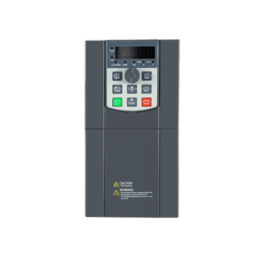
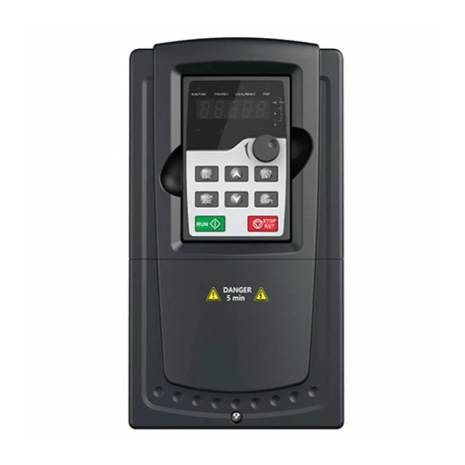
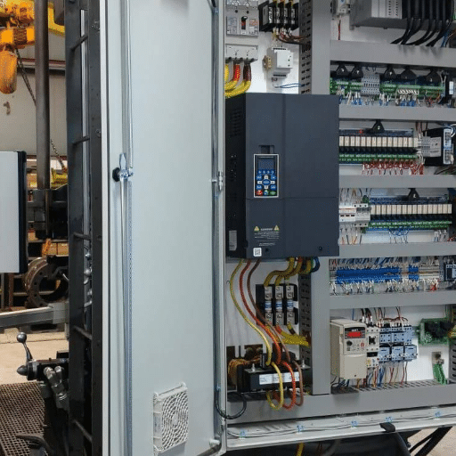
Ready to Get Your VFD Solution?
Whether you need a single drive or a complete system, we have the VFD products and engineering support to ensure your project's success.


VFD configuration is the process of programming a variable frequency drive so it knows what motor it is controlling, how it will receive start and speed commands, and how it should protect itself and the connected load. Get this right and the drive starts quietly, runs efficiently, and rarely trips. Get it wrong and the same drive becomes a source of nuisance overcurrent, overvoltage, and overheating faults that can take days to diagnose.
Marco learned this on a Tuesday morning in a Jakarta packaging plant. A new 22 kW conveyor drive had been wired perfectly, the motor was brand new, and the operator pressed start with confidence. The drive tripped on overcurrent before the belt moved half a meter. The problem was not mechanical, and it was not a bad IGBT. The acceleration time was still at the 0.5-second factory default, and the motor rated current had never been entered. Ten minutes of VFD configuration changes fixed what looked like a hardware failure.
That pattern repeats in plants everywhere. Industry field estimates put roughly 60% of post-installation VFD faults on incorrect motor parameter entry or skipped auto-tuning, not on failed components. This VFD configuration guide gives you a repeatable workflow that prevents those faults before the drive is ever loaded. You will learn how to program a VFD for the first time, choose control modes, set ramps, tune PID loops, configure communication, and hand the system over with a documented parameter backup.
Key Takeaways
- About 60% of post-installation VFD faults come from wrong motor data or skipped auto-tuning, not failed hardware.
- A repeatable commissioning workflow starts with safety, factory reset, motor nameplate entry, ramps, control mode, and a no-load test.
- V/Hz control suits pumps and fans, sensorless vector suits high-starting-torque loads, and closed-loop vector or DTC suits precision applications.
- Built-in PID, communication, and protection parameters should be configured before the drive is handed over to operations.
- Always back up the final parameter set and document what was changed.

VFD configuration is the bridge between installation and production. Installation gets the wires, fuses, and cooling in place. Configuration tells the drive the electrical identity of the motor, the control language it should listen to, and the safety boundaries it must respect.
Configuration is different from troubleshooting and maintenance. Troubleshooting starts after a fault appears. Maintenance starts after the system has run for a while. VFD configuration happens before first run and sets the conditions that make both of those later activities easier or harder. A well-executed VFD configuration exposes useful diagnostic data and trips only when something genuinely needs attention. A poorly configured drive hides real problems behind nuisance trips or, worse, fails to trip when it should.
If you are choosing the drive itself, start with our guide on how to choose the right VFD. Once the right drive is on the bench, this VFD configuration guide takes you from first power-on to a signed-off commissioning report.
Before you touch a keypad, verify that the system is safe to power and that you have the information the drive will ask for. Good VFD configuration starts with safe preparation, not faster typing. Skipping this phase can turn a simple programming session into a safety incident.
Apply lockout/tagout procedures to the incoming supply. Verify zero energy with a qualified meter. VFD DC bus capacitors can hold a lethal charge for five to ten minutes after power is removed, so wait for the drive’s charge indicator to show safe levels or measure the DC bus directly and confirm it is below 50 V before working on the power circuits.
Confirm that input power, motor output, control, and ground wiring match the drive manual. Check that the motor can turn freely, the load is uncoupled or ready for low-speed testing, and the cooling system is clear. A blocked heatsink or disconnected fan will cause an overtemperature trip that looks like a VFD configuration problem but is really an installation issue.
The single most important preparation step is to collect the motor nameplate values. You will need rated voltage, rated current (FLA), rated frequency, rated speed, rated power, and pole count. Enter these values from the motor, not from the supply, the breaker, or the drive’s own rating. For a deeper dive on each value, see our VFD motor nameplate parameters guide.

The first-time VFD programming workflow follows a clear sequence. Skipping steps or changing them out of order is what turns a simple startup into a long afternoon of fault codes. Treat this section as your core VFD parameter setup checklist and your answer to “how to configure a VFD” from power-on to first run.For a step-by-step walkthrough of the keypad screens and menu structure on a typical drive, our complete VFD programming guide expands on each stage of this sequence.
Start from a known state. Most drives have a parameter that restores factory defaults. This removes any settings left by a previous application and gives you a clean slate for VFD configuration. Document the existing parameter set before resetting if you are reconfiguring a used drive.
Enter the five core motor parameters exactly as they appear on the nameplate. This is the most important screen in VFD configuration because every protection, ramp, and control calculation depends on these values:
| Motor Data | Why It Matters | Typical Parameter Group |
|---|---|---|
| Rated voltage | Sets the V/Hz ratio | Motor nameplate voltage |
| Rated current (FLA) | Sets overload and thermal protection | Motor nameplate current |
| Rated frequency | Defines the base frequency | Motor nameplate frequency |
| Rated speed | Used for slip compensation and display | Motor nameplate speed |
| Rated power | Reference for scaling and matching | Motor nameplate power |
Wrong voltage shifts the V/Hz ratio and invites overvoltage or undervoltage trips. Wrong current leaves the motor without real thermal protection. Wrong speed or pole count confuses vector control and makes the displayed RPM inaccurate.
Set the minimum and maximum output frequency. This part of VFD configuration protects both the motor and the driven machine. Minimum frequency deserves special attention on totally enclosed fan-cooled (TEFC) motors because the shaft fan moves very little air below 10 to 15 Hz. A TEFC motor running at 5 Hz can overheat even at light load. Maximum frequency should never exceed what the motor bearings, balancing, and driven machine can tolerate.
VFD ramp settings decide how aggressively the drive changes speed. Too short on acceleration and the drive demands more current than the motor can deliver, causing an overcurrent trip. Too short on deceleration and the motor regenerates energy faster than the DC bus can absorb, causing an overvoltage trip. Getting this part of VFD configuration right saves you from the two most common startup faults.If you want practical formulas for matching ramp times to load inertia, our detailed guide to VFD ramp settings shows how to calculate and fine-tune these values for each load type.
Practical starting points by load are:
| Load Type | Acceleration Time | Deceleration Time |
|---|---|---|
| Centrifugal pump | 5-15 seconds | 5-15 seconds |
| Fan | 10-30 seconds | 10-30 seconds |
| Conveyor | 3-10 seconds | 3-10 seconds |
| High-inertia load | 10-60 seconds | 10-60 seconds or braking resistor |
Enable stall prevention and overvoltage control before shortening ramps. These functions pause the ramp when current or bus voltage climbs, letting you run tighter ramps without trips.
Choose V/Hz, sensorless vector, closed-loop vector, or direct torque control based on the load and accuracy required. This is one of the most consequential decisions in VFD configuration and is covered in detail in the next section. If you are unsure, our dedicated VFD control modes explained article provides a full decision framework.
Tell the drive where its instructions will come from. This part of VFD configuration is often skipped because it feels obvious, but it causes a surprising number of no-run complaints. Common options are the keypad, digital inputs (terminal start/stop), analog input (4-20 mA or 0-10 V), or a fieldbus network. Mixing these sources is a common reason a drive sits idle with no fault code.
Save the parameter set. Run the motor uncoupled or at very low speed first. Check direction, noise, vibration, and current. This no-load test is the only way to confirm that the earlier VFD configuration steps were entered correctly before you connect the load and run to full speed.
The VFD control modes you choose are one of the most important decisions in VFD configuration. They determine how the drive calculates voltage, current, and torque. The four main modes are V/Hz, sensorless vector, closed-loop vector, and direct torque control. For a head-to-head comparison with sizing tips for each option, our full guide to VFD control modes breaks down when to use each one.
| Control Mode | Best For | Speed Regulation | Starting Torque | Encoder Needed |
|---|---|---|---|---|
| V/Hz (scalar) | Pumps, fans, simple conveyors | ±2-3% | 60-80% at 2 Hz | No |
| Sensorless vector | Extruders, mixers, high-starting-torque loads | ±0.5% | 150-200% at 0.3-0.5 Hz | No |
| Closed-loop vector | Winders, tensioning, precision speed | ±0.01% | Full torque at zero speed | Yes |
| Direct torque control (DTC) | Cranes, hoists, high-dynamic test stands | ±0.01% | Full torque at zero speed | Optional/feedback |
V/Hz is simple and forgiving. It can also run multiple motors from one drive, which makes it common in fan and pump applications. Vector modes need accurate motor data and auto-tuning. DTC gives the fastest torque response but requires careful VFD configuration and usually a feedback device.
For a deep comparison, read our VFD control modes explained guide. The important point for commissioning is to match the mode to the job and never leave a vector-capable drive in V/Hz when the application actually needs vector performance.

Ramp tuning is where many VFD configuration sessions succeed or fail. The goal is to move the load as fast as the process needs without exceeding the drive’s current limit or the DC bus voltage limit.
During acceleration, the drive must supply both magnetizing current and torque-producing current. If the ramp is too short, the total current exceeds the drive or motor limit and the drive trips on overcurrent. During deceleration, the motor becomes a generator. If the ramp is too short, the regenerated energy raises the DC bus voltage until the drive trips on overvoltage or fires the braking chopper.
High-inertia loads such as large fans, flywheels, and centrifuges need longer deceleration times or a braking resistor. This is one of the most common points where VFD configuration meets real-world physics. A good rule of thumb is to start with a deceleration time at least equal to the acceleration time, then extend it if overvoltage trips occur. If the process cannot tolerate a long deceleration, size a braking resistor rather than disabling the overvoltage protection.
Some machines have a structural resonance at a specific speed. A pump that vibrates hard at 47 Hz does not need a mechanical rebuild; it may only need a narrow skip frequency band programmed around 47 Hz. This is a simple configuration fix that is often overlooked.
VFD auto tuning, also called motor identification, measures the motor’s electrical characteristics so the drive can control it accurately. The quality of this step directly affects vector control performance and the overall success of VFD configuration. If you are new to the process, our step-by-step guide to VFD auto tuning walks through static and dynamic identification and how to read the results.
Static tuning runs with the motor shaft locked and measures stator resistance and inductance. It is fast and good enough for many V/Hz and light vector duties. Dynamic tuning spins the uncoupled motor and captures back-EMF and inertia data. It is what sensorless and closed-loop vector really need.
| Control Mode | Auto-Tuning Requirement |
|---|---|
| V/Hz | Optional; nameplate data is usually enough |
| Sensorless vector | Required; static or dynamic depending on brand |
| Closed-loop vector | Required; usually dynamic with encoder set first |
| DTC | Required; full motor identification run |
Field surveys cited by industry guides suggest that roughly 80% of engineers either skip auto-tuning or run it incorrectly. The symptoms show up as oscillation, poor low-speed torque, or unexplained overcurrent trips under light load. A packaging line we supported showed exactly why VFD configuration matters: the drive was set to closed-loop vector but had never been tuned, so the speed loop oscillated and tripped. Running a dynamic motor identification with the load uncoupled removed the oscillation and the trips.
Many modern drives include a built-in PID controller. This lets the drive maintain a process variable such as pressure, flow, or temperature by adjusting motor speed automatically. For pump and fan systems, PID is one of the most valuable advanced features in VFD configuration. For a wider view of ramp, control mode, and PID choices tailored to these loads, our dedicated guide to VFD configuration for pumps and fans pulls the whole setup together in one place.
Use built-in PID when the process loop is simple and local. A constant-pressure pump or a constant-temperature cooling tower is a good example. If the loop is complex, cascaded, or part of a larger plant control strategy, a separate PLC or DCS is usually a better home for the PID.
Connect the feedback sensor to the drive’s analog input. Common signals are 4-20 mA for pressure transducers and 0-10 V for level sensors. Set the PID to use that input as feedback, enter the setpoint, and configure the output to drive motor speed.
Start with conservative gains. Set integral time high and derivative to zero. Increase proportional gain until the system responds quickly without excessive overshoot, then reduce integral time to remove steady-state error. Add derivative only if oscillation persists. Also configure sleep and wake functions so the drive stops the motor when demand is low and restarts before pressure collapses. This completes the PID portion of VFD configuration for most pump and fan systems. If you want deeper tuning methods and worked examples, our guide to VFD PID control covers gain selection, sleep/wake logic, and troubleshooting unstable loops.
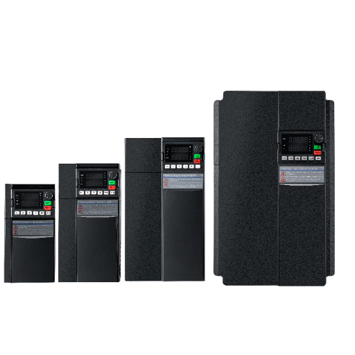
VFD communication configuration is the step that lets a PLC, SCADA system, or building automation system start, stop, and speed-reference the drive remotely. It is often the last major task in VFD configuration before handover.For detailed wiring diagrams and control-word mapping across each protocol, our guide to VFD communication configuration walks through the settings that keep a drive and PLC in sync.
| Protocol | Typical Use | Wiring |
|---|---|---|
| Modbus RTU | PLC integration over RS-485 | Twisted pair, termination at both ends |
| Modbus TCP | Ethernet-based control | Standard Ethernet cable |
| EtherNet/IP | Allen-Bradley / Rockwell environments | Ethernet with managed switch |
| PROFIBUS DP | Siemens / European systems | Shielded Profibus cable |
| PROFINET | Modern Siemens networks | Industrial Ethernet |
Choose the protocol that matches your controller and existing plant standard. Mixing protocols on the same machine because a drive “also supports” one is a common source of confusion.
Baud rate, parity, stop bits, and node address must match the master. On RS-485 networks, termination resistors must be installed at both ends of the bus. Control and status words must be mapped correctly; a start command that uses the wrong bit in the control word will leave the drive idle while the PLC thinks it is running.
Protection parameters are the safety layer of VFD configuration. They decide which faults trip and how fast. They are not obstacles to work around; they are the reason a VFD protects the motor and itself.For threshold-by-threshold guidance on setting each limit correctly, our guide to VFD protection settings explains how to balance nuisance-trip avoidance against genuine motor protection.
Set the overload to the motor FLA and service factor. The drive’s electronic overload can extend motor insulation life by preventing chronic low-grade overheating. Do not enter the drive’s rated current here unless it matches the motor exactly.
Overcurrent, overvoltage, and undervoltage thresholds should generally be left near factory defaults unless the application has a specific reason to change them. Ride-through settings can help the drive survive brief voltage sags without tripping.
Stall prevention pauses acceleration or deceleration when current or voltage limits approach. Safe Torque Off (STO) is a safety function that removes torque-generating power from the motor. If your application needs STO, verify that the drive supports it and that the safety circuit is wired according to the manual.
A commissioned drive without a parameter backup is one firmware update or one failed keypad away from losing its personality. This is why documentation is a non-negotiable part of VFD configuration.For methods that cover keypad, PC-tool, and memory-card backups along with naming conventions, our guide to VFD parameter backup shows how to protect and restore a working configuration.
Spare drives, emergency replacements, and future expansions all need the same parameter set. A backup file lets you clone a working VFD configuration in minutes instead of rebuilding it from notes.
Most drives allow parameter backup through the keypad, a PC tool, or a removable memory card. Save the file with a clear name that includes the drive model, motor tag, date, and version. Store a copy on the plant network and a copy with the drive documentation.
A good handover document is the final step in a professional VFD commissioning process. It should include:
This discipline turns a VFD configuration project into a repeatable, auditable process. For long-term reliability, combine it with our VFD preventive maintenance checklist.
Most VFD configuration mistakes are not exotic. They are the basics done in a hurry, and they are the same mistakes that show up later in our VFD troubleshooting guide. Review this list before you power up your next drive.
Entering the drive rated current or breaker size instead of motor FLA removes real thermal protection. If the motor overloads, the drive may never trip.
A 460 V motor on a 480 V supply should be configured for 460 V. Entering 480 V shifts the V/Hz ratio and can cause overvoltage or saturation issues.
Vector control without tuning is guessing. The result is usually oscillation, poor torque, or nuisance trips.
A TEFC motor left at 0 Hz minimum can run at crawl speed with almost no cooling. The result is repeated overheating faults that seem to come from nowhere.
A drive configured for keypad start will ignore terminal start commands. A drive configured for terminal control will ignore a fieldbus start command. Always verify the active command source before declaring a drive “won’t run.”

Use this checklist on every commissioning job. Print it, check each box, and attach it to the handover documentation. Following a written VFD configuration checklist is one of the simplest ways to avoid the mistakes that cause first-day trips.
| Step | Task | Verified |
|---|---|---|
| 1 | Lockout/tagout and DC bus discharge | [ ] |
| 2 | Wiring, grounding, and cooling check | [ ] |
| 3 | Factory reset to known state | [ ] |
| 4 | Motor nameplate data entered exactly | [ ] |
| 5 | Minimum and maximum frequency set | [ ] |
| 6 | Acceleration and deceleration ramps set | [ ] |
| 7 | Control mode selected and verified | [ ] |
| 8 | Auto-tuning completed if required | [ ] |
| 9 | Command source and speed reference set | [ ] |
| 10 | Protection thresholds reviewed | [ ] |
| 11 | PID configured if used | [ ] |
| 12 | Communication settings matched to master | [ ] |
| 13 | No-load test run completed | [ ] |
| 14 | Loaded test run completed | [ ] |
| 15 | Parameter backup saved and documented | [ ] |
VFD configuration is the process of programming a variable frequency drive with motor data, control modes, ramp times, protection settings, command sources, and communication parameters so it can run a motor safely and efficiently.
At minimum, set motor rated voltage, current, frequency, speed, and power. Then set speed limits, acceleration and deceleration ramps, control mode, command source, and speed reference source. Add protection, PID, and communication settings as the application requires.
Use V/Hz control or sensorless vector, set longer ramps to avoid hydraulic shock, set a minimum frequency that keeps the motor cool, and use a squared V/f curve for centrifugal loads. If the system needs constant pressure or flow, configure the built-in PID with a pressure or flow transducer.
V/Hz control will usually still work. Sensorless vector, closed-loop vector, and DTC will perform poorly or trip on overcurrent because the drive is guessing the motor’s electrical model instead of measuring it.
Use the drive’s keypad utility, manufacturer PC software, or removable memory card to save the parameter set to a file. Name the file clearly and store copies with the drive documentation and on the plant network.
Use the protocol that matches your PLC or automation platform. Modbus RTU is common and simple. EtherNet/IP fits Rockwell environments. PROFIBUS and PROFINET fit Siemens environments. Modbus TCP is a flexible Ethernet option.
VFD configuration is not a side task in commissioning. It is the foundation that determines whether the drive runs cleanly for years or becomes a recurring source of mysterious trips. The workflow is straightforward: make it safe, reset to defaults, enter real motor data, set ramps and limits, choose the right control mode, run auto-tuning when required, configure PID and communication if needed, verify protection settings, and save a documented backup.
The real value is not just fewer faults. It is a drive that protects the motor, matches the process, and gives operators and maintenance teams useful information when something does go wrong. If you have completed this guide and want to understand what happens when configuration errors slip through, our complete VFD troubleshooting guide maps every common fault back to its cause.
If you need help selecting, configuring, or commissioning a VFD for your application, the Shandong Electric engineering team can support you from specification to startup. Contact us to discuss your project.