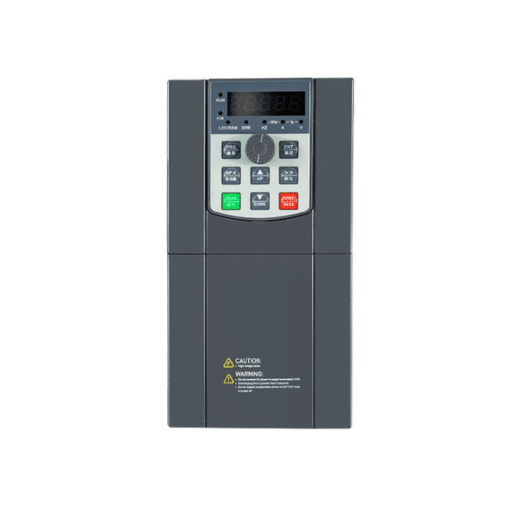
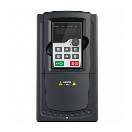
Ready to Get Your VFD Solution?
Whether you need a single drive or a complete system, we have the VFD products and engineering support to ensure your project's success.

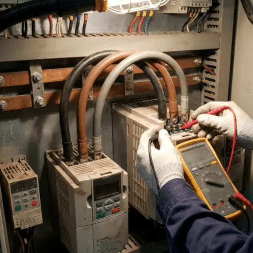
VFD troubleshooting is the systematic process of identifying why a variable frequency drive has tripped, failed to start, or produced an alarm, then correcting the root cause rather than simply resetting the fault. The most effective approach combines fault-code interpretation, electrical measurement, parameter verification, and a clear understanding of what changed.
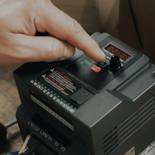
Last Friday at 4:30 p.m., the packaging line at a food plant in Ohio stopped dead. The operator looked at the drive keypad, saw “E. OC1” flashing, and pressed reset. The drive ran for eight minutes and tripped again.
A frustrated maintenance tech replaced the drive on Saturday morning, only to watch the new one trip the same way. On Monday, an engineer spent 20 minutes with a multimeter and discovered a seized conveyor roller. The drive was never the problem. The lesson cost a weekend of overtime.
This guide gives you a practical, repeatable method for VFD troubleshooting. It covers the four questions every technician should ask, how to read fault codes across manufacturers, the most common faults, and when to repair or replace the drive.
Key Takeaways
- Always record the fault code and operating state before resetting a drive; blindly resetting hides the root cause.
- The four diagnostic questions are: what was the drive doing, what is the fault code, what changed recently, and does the fault repeat with the motor disconnected?
- About 60% of post-installation VFD faults trace back to incorrect parameters, not hardware failure.
- Overcurrent is the most common fault category, accounting for 35-45% of all trips.
- Use the printable checklist at the end of this guide to make every troubleshooting call consistent and safe.
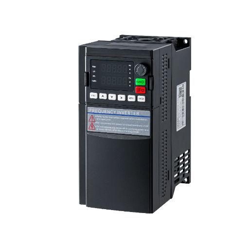
Troubleshooting begins before you open the enclosure. The golden rule is simple: understand the fault before you clear it.
Always follow site lockout/tagout procedures. Verify zero energy by measuring voltage at the input terminals, checking the DC bus with a properly rated meter, and waiting the manufacturer-specified discharge time. Capacitors in the DC bus can hold a lethal charge for several minutes after power is removed.
If you are not authorized to work on live industrial equipment, stop here and escalate. No checklist replaces qualified personnel and safe work practices.
The fault code is the drive’s attempt to tell you what it detected. Pressing reset erases that message. Take a photo of the display. Note the operating state at the moment of trip: accelerating, running at speed, decelerating, or idle. This context determines whether the cause is mechanical, electrical, or parameter-related.
This framework prevents the random parts-swapping that wastes time and money. Use it on every call.
A water treatment plant in Durban used this exact sequence when a pump drive tripped on overvoltage every afternoon. The code pointed to regenerative energy during decel.
The recent change was a new pump with a faster coast-down. Adding a correctly sized braking resistor solved the problem in an hour. No drive replacement needed.
Fault codes vary by manufacturer, but the underlying conditions are universal. Learning to translate codes by symptom lets you work on any drive brand.
| Fault Type | ABB | Siemens | Mitsubishi | Yaskawa | Danfoss | Delta |
|---|---|---|---|---|---|---|
| Overcurrent | 2310 | F0001 | E. OC1/2/3 | oC | 4, 13 | oc |
| Overvoltage | 3210 | F0002 | E. OV1/2/3 | ov | 7 | ov |
| Undervoltage | 3220 | F0003 | E. UVT | Uv1/2/3 | 8, 14 | uv |
| Overtemperature | 4210 | F0004/F0011 | E. FIN/E. OHT | oH | 29 | oH |
| Ground Fault | 2330 | F0026/F0027 | E. GF | GF | 14, 22 | gF |
| Output Phase Loss | 3130 | F0018 | E. LF | PF | 15 | oL |
| External Fault | 9001 | F0020 | E. EF | EF | 17 | EF |
Use this table as a starting point, not a final diagnosis. A single code can have multiple causes, and some faults produce misleading codes when the real issue is a failed sensor or bad connection.
Fault codes describe what the drive measured, not necessarily what failed. An undervoltage fault during a utility sag is accurate. An undervoltage fault caused by a loose input terminal is misleading until you measure it. Always confirm the code with a meter before ordering parts.
Most VFD faults fall into four categories: current, voltage, temperature, and connection. The sections below summarize each category and link to deeper guides where available.
Overcurrent means the output current exceeded the drive’s limit. Causes include mechanical jam, shorted motor winding, damaged cable, acceleration ramp too short, incorrect motor current setting, or a failed output IGBT. For a full diagnostic procedure, see our guide to VFD overcurrent fault.
A maintenance team at a steel mill spent two days chasing an intermittent overcurrent trip. The motor spun freely by hand. The cable insulation looked fine.
A megger test finally revealed a phase-to-ground fault that only appeared when the cable moved during operation.
Overvoltage usually means the DC bus rose above the limit. Regenerative energy during rapid deceleration is the most common cause. Other causes include missing braking resistor, oversized decel ramp, or high input line voltage. See our guide to VFD overvoltage fault for detailed steps.
Undervoltage points to low DC bus voltage. Check for utility sags, loose input connections, blown fuses, bad contactor, or aging DC bus capacitors. If the fault happens only under load, measure voltage at the drive terminals while the drive is running. A small voltage drop at the panel can become a large drop at the drive under load. For a full diagnostic procedure, see our guide to VFD undervoltage fault.
Overtemperature protects the drive’s heatsink or inverter module. Common causes are blocked heatsink fins, failed cooling fan, high ambient temperature, or excessive carrier frequency. Clean the heatsink, verify fan rotation, and improve ventilation before assuming the drive is failing.
For every 10°C above rated temperature, semiconductor life approximately halves. A dirty heatsink is not just a nuisance trip. It is an accelerated aging problem.If your drive keeps overheating even after you clean the heatsink and confirm the fan works, our dedicated guide to the VFD overheating fault walks through carrier frequency, ambient conditions, and cooling design in much greater depth.
Ground fault indicates current leaking from the output to earth. The usual suspects are motor insulation breakdown, moisture in a junction box, damaged cable, or long motor cable runs without an output reactor. A megger test on motor and cable should read greater than 5 MΩ at 500 V DC. Lower readings point to insulation damage.For a step-by-step method to trace leakage current back to its source, our detailed guide to the VFD ground fault covers megger testing, cable length effects, and how to isolate the motor from the drive during diagnosis.
Phase loss means the drive detects an open circuit on one output phase. Causes include loose output terminal, open motor winding, blown fuse, or failed IGBT. Measure continuity through the motor and cable, and inspect terminals for discoloration or heat damage.
A drive that shows no fault but refuses to run is often more frustrating than one that trips. The cause is usually in the control circuit or parameters. Our detailed guide covers this scenario in depth: VFD not running.
Check whether the drive is in local/keypad mode or remote/terminal mode. A common commissioning mistake is setting the control source to communication or terminals while testing from the keypad. The display may look normal, but the drive never sees a valid run command.
Many drives use safe torque off (STO) inputs. If a safety contactor or e-stop chain is open, the drive will not start. Measure the STO input voltage and verify the safety chain is complete.
A drive with a valid run command but zero frequency reference will not accelerate. Verify the analog input signal, potentiometer setting, or communication register providing the speed reference.
If the motor hums but does not rotate, suspect single-phasing, a failed capacitor on a single-phase system, or a seized mechanical load. Check voltage across all phases and try turning the motor shaft by hand.
Modern VFDs spend as much time talking to PLCs as they do running motors. When communication fails, the drive may stop, ignore commands, or report a communication fault.
The most common Modbus problems are wrong baud rate or parity, missing termination resistor, duplicate node addresses, and incorrect shield grounding. Start by verifying the basic settings match the PLC. Add a 120 Ω termination resistor at the end of the bus. Ground the shield at one end only to avoid ground loops.When these basic checks do not clear the alarm, our dedicated guide to the VFD communication fault digs deeper into network topology, noise immunity, and register mapping between the drive and PLC.
A 4-20 mA speed signal that drops to 0 mA can cause the drive to stop or run at minimum speed. Check the loop power supply, wire continuity, and whether the sensor is in fault state. Many drives allow you to set a fault response for analog signal loss.

Incorrect parameters are responsible for roughly 60% of post-installation VFD faults. This makes parameter review one of the highest-value troubleshooting steps.
Verify that motor rated voltage, current, frequency, speed, and power match the nameplate. Entering a lower current rating than the motor actually draws will cause nuisance overload trips. Entering a higher rating removes protection.
An acceleration ramp set too short causes overcurrent trips. A deceleration ramp set too short causes overvoltage trips. The correct ramp time depends on load inertia, not just a number copied from another drive.
V/f control is simple and robust but provides lower torque at low speed. Vector control gives better performance but requires motor data and often an auto-tune. Using vector control without proper tuning can cause instability or current faults. Our VFD parameter settings guide explains how to set these correctly.
Minimum and maximum frequency limits can prevent a drive from starting or reaching full speed. Check parameter settings for forward/reverse enable and frequency limits before assuming hardware failure.
Good diagnosis depends on the right tools. Keep these on hand for every VFD service call.
The best troubleshooting call is the one you never have to make. A structured preventive maintenance program catches problems before they stop production.
For a complete maintenance schedule, see our VFD preventive maintenance guide.
When a drive has a repeated or catastrophic fault, you face a decision: repair, replace, or escalate. Use this framework to avoid emotional decisions.
Repair makes sense for minor issues: failed cooling fan, blown input fuse, loose connections, or parameter corruption. These are fast, low-cost fixes. If the drive is less than 10 years old and the fault is isolated, repair is usually the right call.
Replace the drive when the power stage is damaged, repeated IGBT failures occur, spare parts are obsolete, or the repair cost exceeds 50-60% of a new drive.
Also consider replacement if the drive lacks modern features needed for the application, such as network connectivity or improved protection functions.
Call the manufacturer or a qualified service partner when you see repeated unexplained faults, damaged printed circuit boards, or when the drive is still under warranty. Opening the drive yourself may void warranty coverage.
Use this text flowchart as a quick decision aid in the field.
Drive faulted or will not run
 |
 v
Record fault code and operating state
 |
 v
Is there a fault code?
 |-- Yes --> Match code to current / voltage / temp / ground / comm / parameter
 | |
 | v
 | Apply the 4-question framework
 | |
 | v
 | Does fault repeat with motor disconnected?
 | |-- Yes --> Check drive input, DC bus, internal hardware
 | |-- No --> Check motor, cable, mechanical load, parameters
 |
 |-- No --> Check control source, run command, frequency reference, safety circuit
This flowchart works because it separates drive problems from system problems early. Most technicians skip that step and waste hours on the wrong component.
Sometimes the drive is fine but the power around it is not. Voltage sags account for approximately 30% of unplanned industrial downtime in motor-drive systems. Harmonics from other drives can cause erratic behavior, overheating, and false trips.
If faults are intermittent or correlated with other equipment switching on, measure power quality. A power quality analyzer can reveal sags, swells, transients, and harmonic distortion that no amount of parameter tuning will fix. For harmonic-related issues, see our guide on high voltage VFD harmonics.

Use this checklist on every service call to stay consistent.
VFD troubleshooting is the systematic process of identifying why a variable frequency drive has tripped, failed to start, or generated an alarm, then correcting the root cause rather than only resetting the fault.
The most common faults are overcurrent, overvoltage, undervoltage, overtemperature, ground fault, and output phase loss. Communication and parameter errors are also frequent.
Overcurrent trips are usually caused by mechanical overload, shorted motor or cable, acceleration ramp too short, incorrect motor current setting, or failed output IGBT.
Check the control source, run command, frequency reference, and safety circuit. Many no-start issues are control problems, not drive failures.
Fault codes are displayed on the drive keypad or communication interface. Cross-reference the code with the manufacturer manual, or use the brand-agnostic table in this guide to identify the fault category.
Repair when the fault is minor and isolated, such as a failed fan, blown fuse, loose connection, or parameter corruption. Replace when the power stage is damaged, parts are obsolete, or repair cost exceeds roughly half the cost of a new drive.
A true-RMS multimeter, megger, clamp-on ammeter, thermal camera, and power quality analyzer are the core tools. The manufacturer manual is also essential.
Regular maintenance including heatsink cleaning, fan inspection, terminal re-torquing, parameter backup, and motor insulation testing prevents most common faults.
Common causes are incorrect baud rate or parity, missing termination resistor, duplicate node addresses, poor shield grounding, and cable length issues.
This usually indicates single-phasing, a failed start capacitor in single-phase systems, or a seized mechanical load. Check voltage balance and shaft rotation.
VFD troubleshooting is not about memorizing fault codes. It is about asking the right questions, measuring before replacing, and separating drive problems from system problems. The four-question framework, the cross-manufacturer fault-code table, and the printable checklist in this guide give you a repeatable process that saves time and money.
Start every call with safety. Record the code before resetting. Verify parameters. Measure voltage, current, and insulation. Only then decide whether to repair, replace, or escalate. If the problem is complex or repeated, contact the Shandong Electric engineering team for application support. We can help you diagnose the fault, select the right replacement or protection, and get your line running again.
For quick reference on common field issues, see our existing guides on VFD troubleshooting common issues and common VFD problems. For product and support information, visit our VFD products page.