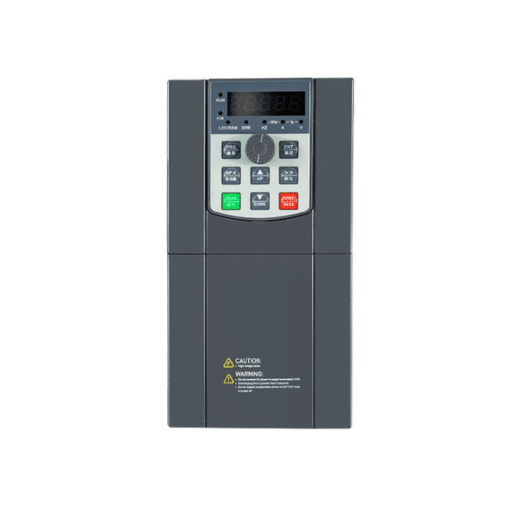
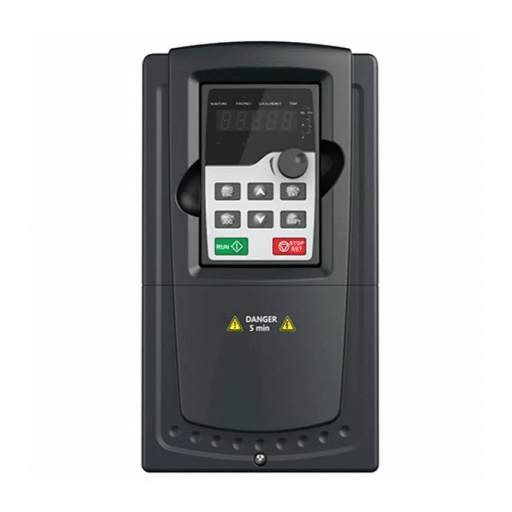
Ready to Get Your VFD Solution?
Whether you need a single drive or a complete system, we have the VFD products and engineering support to ensure your project's success.


A high-power VFD system is an integrated assembly that stretches from the input transformer to the motor terminals. It includes the drive, cooling, protection, control, and often harmonic mitigation. Specifying the drive cabinet is only part of the job. The system around it determines reliability, efficiency, and ROI.
Many procurement teams treat a megawatt-class drive as a single SKU. In reality, the transformer, cable, cooling method, and protection coordination can have a larger impact on performance than the converter itself. A mismatch between topology and motor type, or between cooling capacity and losses, can turn a promising retrofit into a long-term maintenance problem.
This guide explains how high-power VFD systems work, what components they include, which topologies fit which applications, and how to avoid the integration mistakes that plague large drive projects.
Key Takeaways
- A high power VFD system includes transformer, converter, motor cable, cooling, protection, and control, not just the drive cabinet.
- Common topologies include CHB, NPC, MMC, CSI, and LCI, each suited to different voltages, power levels, and motor types.
- Applications span power generation, steel, cement, mining, water, and oil & gas.
- System efficiency depends on transformer losses, cable losses, harmonics, and cooling power, not just drive headline efficiency.
- Integration mistakes such as undersized transformers, ignored harmonics, and poor bypass planning are common causes of project failure.

In industrial practice, high-power VFD systems usually refer to medium-voltage adjustable-speed drives rated from roughly 1 MW to 25 MW or more, operating at voltages from 2.3 kV to 13.8 kV. True high voltage drives above 35 kV are rare outside utility or traction systems.
A complete system includes:
The drive cabinet is the core, but it cannot function well without the surrounding infrastructure. Transformer impedance affects voltage regulation and harmonics. Cable length affects voltage reflections. Cooling capacity determines whether the drive can sustain rated output in summer ambient temperatures.
When Ana Petrova, a project engineer at a Bulgarian cement plant, compared quotes for a 3.3 kV, 2,500 kW kiln drive, the lowest-priced option omitted the output reactor. It also specified a smaller transformer than competitors. After installation, the drive tripped on overvoltage during deceleration. It also produced enough harmonic current to overheat the plant power factor correction capacitors. The cost to add the missing components exceeded the original price difference.
Want a foundation on voltage class and topology? Start with our complete guide to high voltage VFDs for selection principles across 2.3 kV to 13.8 kV applications.
Understanding each component helps explain why system integration matters more than drive selection alone.
Most medium voltage drives use an input transformer to step down the plant supply voltage and provide isolation. Cascaded H-bridge designs use a phase-shifting transformer with multiple secondary windings. These windings cancel harmonics at the source. Active front-end designs can eliminate the transformer but add input reactors and active switching devices.
Transformer impedance, typically 4-8%, must be matched to the drive. Too low and fault currents rise. Too high and voltage sag during acceleration can limit torque.
The converter changes fixed-frequency AC into variable-frequency AC. Semiconductor devices such as IGBTs, IGCTs, or IEGTs switch at high frequency to synthesize the output waveform. The choice of device and topology determines efficiency, harmonic performance, and motor compatibility.
Output reactors limit dV/dt at the motor terminals and reduce cable charging current. Sinusoidal filters further smooth the waveform. For long motor cables or older motors, these components are essential to protect insulation.
High power systems use shielded medium voltage cable with proper stress control terminations. Cable length, shield grounding, and routing all affect EMI and voltage reflections. For detailed guidance, see our article on high voltage VFD installation requirements.
Air-cooled systems use filtered intake and exhaust fans. Water-cooled systems use deionized coolant, pumps, and heat exchangers to move heat out of the electrical room. Cooling must be sized for total losses, including transformer and auxiliary losses. For a deeper comparison, read our water-cooled VFD guide.
Protection relays coordinate with upstream breakers and downstream motor protection. Control systems integrate with PLCs or DCS through Modbus, Profibus, Ethernet/IP, or proprietary protocols. Proper integration prevents nuisance trips and enables remote monitoring.

Topology determines voltage capability, harmonic performance, efficiency, and motor compatibility. The table below summarizes the most common options.
| Topology | Typical Voltage | Typical Power | Key Strength | Best For |
|---|---|---|---|---|
| Cascaded H-Bridge (CHB) | 3.3-13.8 kV | 1-25+ MW | Low harmonics, mature | Pumps, fans, compressors |
| 3-Level NPC | 2.3-4.16 kV | 0.5-5 MW | Compact, cost-effective | Lower MV applications |
| Modular Multilevel Converter (MMC) | 6.6-13.8 kV | 5-50+ MW | High efficiency, clean waveform | Very large drives |
| Current Source Inverter (CSI) | 2.3-7.2 kV | 1-10 MW | Robust short-circuit handling | High torque, conveyors |
| Load Commutated Inverter (LCI) | Up to 13.8 kV+ | 5-50+ MW | Very high power synchronous motors | Large compressors, mills |
CHB drives connect multiple low-voltage cells in series to reach medium voltage. Each cell has its own rectifier and capacitor fed from a phase-shifted secondary winding. The multi-pulse input transformer cancels many harmonics, so THD at the point of common coupling is often below 3% without external filters.
CHB is the workhorse of high power VFD systems for pumps, fans, and compressors. It is mature, modular, and relatively easy to maintain because individual cells can be replaced.
Neutral Point Clamped inverters use a shared DC bus and clamping diodes to produce three output voltage levels. They are compact and cost-effective at lower medium voltages. However, they produce more harmonics than CHB or MMC and often require output filters for long cables.
MMC topologies use many submodules stacked in series. They offer excellent waveform quality, high efficiency, and scalability to very high voltages and powers. MMC is increasingly used in large drives above 5 MW where harmonic performance and motor-friendly waveforms matter.
CSI drives use a large DC link inductor to feed current to the inverter. They are inherently rugged and handle short circuits well. The output waveform is closer to sinusoidal than voltage-source PWM, so motor stress is lower. CSI is often chosen for high-torque applications such as conveyors and crushers.
LCI drives are used with synchronous motors at very high power. The motor back-EMF commutates the thyristors, so switching losses are low. LCI systems dominate in large compressor and grinding mill applications above 10 MW.
High power VFD systems appear wherever large motors need variable speed, soft starting, or process control.
Boiler feed pumps, induced draft and forced draft fans, cooling water pumps, and gas turbine starters all use medium voltage drives. Removing heat from the electrical house and precise speed control improve plant efficiency. Learn more in our guide to VFD for power plants and heavy industry.
Rolling mill main drives, blast furnace blowers, and process fans operate in hot, dusty, and vibration-prone environments. Water-cooled high power VFD systems are common here because sealed cabinets keep dust away from electronics.
Kiln drives, raw mill fans, and high-temperature process fans need reliable motor control near abrasive dust. A properly integrated VFD system reduces mechanical stress and energy use while surviving harsh conditions.
SAG mills, ball mills, crushers, and conveyors operate at high altitude, wide temperature swings, and heavy dust loads. Direct medium voltage drives reduce cable losses and starting current compared with low voltage plus step-up transformer systems. For more on this sector, see our article on industrial high voltage drives for mining.
Large pumping stations use VFD systems to match flow to demand, reducing energy and water hammer. The combination of affinity laws and variable speed often delivers 20-40% energy savings.
Compressors, pumps, and extruders in upstream, midstream, and downstream operations benefit from precise speed control and reduced mechanical stress. Hazardous-area installations require enclosures certified to IEC 60079 or GB 3836.

The difference between a reliable system and a problematic one usually appears in integration details.
Size the transformer for drive rated current plus harmonic heating. Match impedance to the drive manufacturer’s recommendation. A transformer that is too small causes voltage sag and overheating. One that is too large raises fault current and cost.
High power drives can inject harmonic currents into the plant grid. IEEE 519 and IEC standards set limits on distortion at the point of common coupling. Three common mitigation methods exist:
Ignoring harmonics can damage capacitors, transformers, and other sensitive equipment.
VFDs typically operate at near-unity power factor at the drive input, but the overall plant power factor must still be evaluated. Transformer magnetizing current and reactor inductance can affect reactive power demand.
Motor cables in high power VFD systems must be VFD-rated with metallic shields and stress-control terminations. Long cables can create voltage reflections that damage motor insulation. Output reactors or dV/dt filters are needed for runs above roughly 100-150 meters.
Proper grounding of the transformer, drive cabinet, cable shields, and motor case controls EMI and bearing currents. For voltage-source PWM drives, shield grounding at both ends is often recommended, but always follow the manufacturer.
Calculate total system losses, not just drive losses. A 10 MW drive at 97% efficiency still dissipates 300 kW. Then add transformer losses, reactor losses, and auxiliary power. The electrical room ventilation or liquid cooling system must handle the total heat load under worst-case ambient conditions.
For critical applications, plan a manual or automatic bypass so the motor can run across the line if the drive is out of service. N+1 cooling pumps, redundant fans, and spare power cells can also reduce downtime. Failing to plan bypasses is a common cause of lost production during maintenance.
At a steel mill in Turkey, a 6.6 kV fan drive had no bypass. When the drive needed a firmware update, the fan had to stop, forcing a partial production shutdown. After installing a contactor-based bypass, maintenance could be performed without interrupting the process.
Protection coordination is essential in high power VFD systems because fault energy is large and downtime is expensive.
Upstream circuit breakers or fuses must clear faults without damaging the drive or transformer. Relay settings must coordinate with the drive’s own overcurrent and ground-fault protection.
Motor protection relays monitor thermal overload, phase imbalance, bearing temperature, and vibration. These relays operate independently of the drive to protect the motor during bypass or drive fault conditions.
This driver features overcurrent, overvoltage, undervoltage, overtemperature, and ground fault protection. Modern drivers also monitor semiconductor health, coolant flow, and insulation resistance.
Most high power VFD systems interface with a plant DCS or PLC. Common protocols include Modbus RTU/TCP, Profibus DP, Profinet, Ethernet/IP, and IEC 61850. The speed reference, start/stop commands, and status feedback must be mapped carefully to avoid erratic behavior.
The drive’s headline efficiency number is only part of the story. High power VFD systems must be evaluated on system efficiency and total cost of ownership.
System efficiency includes:
A direct medium voltage drive often beats a low voltage drive plus step-up transformer by 2-4% at the system level, especially over long cable distances. For a detailed breakdown, see our guide on high voltage VFD efficiency.
Modular topologies such as CHB allow cell replacement without stopping the drive. Water-cooled systems eliminate fan and filter maintenance but add coolant monitoring. Spare parts strategy should include power cells, fuses, control boards, and cooling pumps based on lead time and criticality.
For heavy variable-torque loads with high operating hours, payback is often 1-3 years. Energy savings, demand charge reduction, and lower maintenance all contribute. For constant-torque or continuously loaded applications, the business case depends more on process benefits and reliability than energy savings alone.

Learning from real projects prevents expensive rework.
A transformer sized only for motor full-load current may overheat from harmonic currents and voltage sag during acceleration. Always follow the drive manufacturer’s transformer specification.
Adding power factor correction capacitors near a VFD can create resonance at harmonic frequencies. A harmonic study prevents amplification and equipment damage.
Long motor cables without reactors or filters can cause reflected waves that stress motor insulation. Address this in the design phase, not after motor failure.
Sizing HVAC only for drive losses and ignoring transformer and auxiliary losses is a common error. Total system losses determine cooling load.
Critical drives need a bypass path. Without it, every drive maintenance event becomes a production stop.
High power systems require insulation testing, phasing checks, no-load tests, load tests, and thermal imaging. Skipping steps leads to early failures. For a detailed procedure, see our VFD testing and commissioning checklist.
Need help designing a complete system? Contact the Shandong Electric Engineering team for system architecture review, component sizing, and commissioning support.
A high power VFD system is an integrated assembly that includes the input transformer or reactor, power converter, output filter, motor cable, cooling system, protection, and control needed to vary the speed of a large motor, typically from 1 MW to 25+ MW.
Industrial high power VFD systems typically operate from 2.3 kV to 13.8 kV, which is the medium voltage range. True high voltage drives above 35 kV are uncommon outside specialized applications.
The best topology depends on voltage, power, motor type, and application. A cascaded H-bridge is common for pumps and fans. MMC suits very large drives requiring clean waveforms. CSI is robust for high-torque loads. LCI is used for very large synchronous motors.
Major industries include power generation, steel, cement, mining, water and wastewater, and oil and gas. Any application with large motors that benefit from variable speed or soft starting is a candidate.
The transformer provides voltage step-down, isolation, and harmonic cancellation. Its impedance and rating must match the drive to avoid voltage sag, overheating, and poor harmonic performance.
Cooling must handle total system losses, including drive converter losses, transformer losses, reactor or filter losses, and auxiliary power. Air-cooled systems need filtered intake and exhaust; water-cooled systems need pumps, heat exchangers, and coolant monitoring.
Key standards include IEEE 1566 for medium voltage drive performance, IEEE 519 for harmonic limits, IEC 61800-5-1 for safety, and IEC 61800-4-2 for system and installation requirements.
High power VFD systems are integrated engineering projects, not commodity purchases. A reliable system starts with the right topology and transformer, continues with correct cable, grounding, and cooling design, and finishes with coordinated protection and thorough commissioning.
The most expensive mistake is focusing only on the drive cabinet while treating the rest of the system as secondary. A few hours of system-level planning can prevent weeks of downtime, equipment damage, and lost production.