Ready to Get Your VFD Solution?
Whether you need a single drive or a complete system, we have the VFD products and engineering support to ensure your project's success.


Variable Frequency Drives (VFDs), one of the most advanced industrial equipment, are the backbone of the running industrial and commercial systems, as they provide high precision control of motors, thus improving both energy efficiency and operational life of systems. At the same time, a proper and safe VFD system operation could only be achieved with a perfect testing and commissioning process. This guide is meant to be the one that engineers, technicians, and project managers can refer to and go through the essentials of verifying the proper installation, checking the equipment’s functionality, and optimizing the entire system with VFDs. In the process, you would be able to reduce losses of any kind, operational or financial, and also put your business in line with the industry standards. This article will provide you with the significant elements of a successful VFD testing and commissioning strategy.

Variable Frequency Drive (VFD) is a crucial tool for adjusting the speed and torque of electric motors and, consequently, the motor’s input frequency and voltage. The significance of this device in commissioning is immense, as it not only can save energy but also leads to a longer life span of equipment and effective motor performance. Commissioning of VFDs has to be done correctly as it ensures the right installation, pinpoints any possible problems at an early stage, and tailors system operation to the requirements of the application. It is by this means that the process of commissioning brings back into compliance the operational standards while at the same time increases the reliability and safety of the system as a whole.
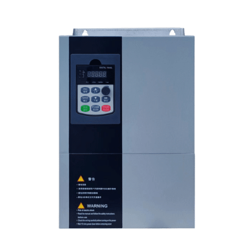
A Variable Frequency Drive (VFD) is an electronic equipment that gains control over the speed and torque of an electric motor by adjusting the frequency and voltage of the power fed to the motor. These drives are very useful in a large number of applications to facilitate precise control of motor operation, reduce energy consumption and overall manufacturing costs, and increase process efficiency. The areas that benefit the most from the application of these drives are HVAC systems, industrial machinery, pumping systems, etc. Such devices are deemed to be the ones that provide mechanical wear reduction, as well as energy cost minimization, on one hand making it very affordable, and on the other ensuring that motor performance is what the specific application requires. Not to mention, apart from that, VFDs have been of great help in reducing the environmental impact coming from carbon emissions. In manufacturing, VFDs are considered the best choice in terms of sustainability.
Variable frequency drives (VFDs) offer the utility of bringing down energy consumption as one of the most notable advantages. The energy wastage linked to full-speed operation if not needed is the case in point for running the electric motor at a speed to match the operational requirement, and this is where VFDs play a role. It has been shown by studies that applying VFDs can lead to a cut down of energy use by 20% to 50% in service-oriented and other units, and it depends on the load and type of motors considered.
In overall assessments, energy savings measures like VFDs have a very positive effect because the life of mechanical parts is greatly extended due to smooth motor starts and reduced operation stress. The life of a motor is shortened due to the presence of sudden voltage spikes and torque surges, but VFDs prevent or at least significantly reduce them, doing less damage to the windings, belts, and gears of the motor, which translates to a decreased number of mechanical failures and hence lower maintenance costs.
Through variable frequency drives (VFDs), operators get precise control of motor speed, torque, and direction. This precise control feature is totally essential in applications that need high accuracy like the conveyor system, mixer, and pumps. Real-time adjustability of motor parameters guarantees the best performance and consistent product quality that are the two important factors if elevated ergonomics and efficiency are aimed at the same time.
Peak power consumption is effectively reduced by virtually all direct motor starts; the reduction takes place because, in any case, we are eliminating the usually not at all seen high inrush currents that are present in the said method. The advantage of using VFDs is not only in the area of the grid but in the utility’s demand charges as well thus dropping the cost for large motor-driven facilities.
The automatic control functionalities present in VFDs increase safety levels by averting events like excessive temperatures, overloads, and system dysfunctions. Fault detection systems combined with real-time feedback thus minimize the surprise element in the maintenance and ensure the continuous flow of activities.
Numerous governments and regulatory institutions put pressure on companies to comply with strict energy efficiency measures regarding the use of machinery. By controlling and reducing the energy consumption of electrical installations through operation, VFDs make it possible to comply with such laws. While certain regulations, including the Ecodesign Directive of the European Commission or energy efficiency standards set by the U. S. Department of Energy (DOE), may indeed be opposed to, VFDs are designed, from the construction phase, to be in accordance with the same.
It is a must to have very precise and complete motor’s data in order to achieve the best performance possible and to have the biggest compatibility between the motor and VFD. The first step is to take the motor’s nameplate details. Generally, these details are the most significant ones like rated voltage, current, frequency, speed (RPM), power rating (kW or HP), and efficiency class. Furthermore, note if the motor is meant for the applications of constant or variable torque since this affects VFD configuration.
Examine the motor’s insulation class and thermal protection tolerance and find out any possible restrictions operating under variable speed. Also, (if you want) analyse and measure rotor resistance and stator inductance of the motor through a motor analyzer for more effective performance tuning. The obtained data very much helps in VFD setting optimization making the system operation stable and highly efficient. Knowing the power of the connected load, like centrifugal, resistive, or constant, is equally important as this significantly impacts the torque and acceleration curves.
Finally, consider the environmental factors of the motor and VFD. This part can involve, for instance, the effects of high and low temperatures, the amount of dust in the air, and the possibility of being exposed to moisture or chemicals, all of which can directly or indirectly influence the motor life and the VFD setting. Through such a rigorous approach to collecting motor information, it will be ensured that the VFD will be best suited for the energy-efficient performance condition, and the motor and the related systems will, at the same time, truly enjoy the reliability ensured throughout the period.

To get the best performance from Variable Frequency Drives (VFDs), it is utterly important to have the parameters accurately set. The next provided parameters should be very carefully adjusted:
These variable settings will result in increased energy savings, longer life of equipment, and compliance with the operational requirements. The user should always look up the manufacturer’s specific VFD manual to see if the drives are compatible with the system and find the necessary application guidelines.
Panel and wiring checks constitute a significantly essential stage in assuring that the operational and safe performance of Variable Frequency Drives (VFDs) is maintained. Elevate the process by validating that all the wiring connections are in compliance with the manufacturer’s specifications. This includes the use of proper torque values on terminal screws to avoid the creation of loose connections or the occurrence of deliberate electrical faults. Evaluate the panel layout for neat cable management — these steps will prevent the interference that is sometimes caused by electromagnetic fields generated by adjacent equipment.
Make sure the input power wiring matches the voltage rating and phase configuration that the VFD is specified in the application. Grounding and bonding shall adhere to the set electrical codes, a recommended practice is to make the path from the ground to the equipment as short and as wide as possible, to reduce the impedance offered to the signal line. Moreover, locate and evaluate control wiring, ensuring that any analog and digital signals are properly shielded to prevent external signal distortion.
Test the motor and the power cables by performing an insulation resistance test first to make sure that there is no damage or degradation. If it is necessary to use long motor leads, then go for the cables with the proper ratings and the addition of a line reactor or dv/dt filter to stop the influence of the reflected wave phenomena. Lastly, survey the cooling system of the panel to provide sufficient ventilation as the drive’s lifetime and operational stability could be severely affected when the operating temperature is higher than recommended.
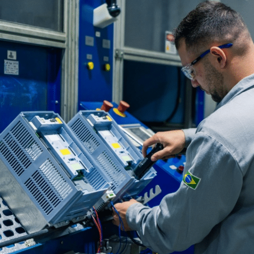
In order to warrant that a Variable Frequency Drive (VFD) maintains its level of reliability and power efficiency, the only way to do it is through the in-depth load testing and performance evaluation. This process requires the VFD to be subjected to the typical and peak loads so that the capability to handle the real-world demands efficiently is made known. Besides, during this exercise, the most common metrics to be observed and compared with the original internal standards are torque output, speed consistency, and power factor.
Sophisticated monitoring devices are applicable for gathering data on power consumption, heat production, and harmonic distortion when in operation. These are the three metrics that matter in scaling industry standards, like IT and electrical design codes and specifications. Furthermore, the evaluation of performance should be supported by stress testing during that time, sudden load changes or power interruptions take place, to have the VFD’s stability and fault tolerance validated. In fact, running the VFD (Variable Frequency Drive) under test load conditions for some time could result in tests that are more reliable and comparable to actual in-use conditions than tests when the load changes are abrupt, making the stress test more meaningful.
Communication testing is crucial to guaranteeing the smooth integration and operational efficacy of Variable Frequency Drives (VFDs) and control systems. Among the various standardized communication protocols of the recent drives, Modbus, PROFIBUS, EtherNet/IP, and BACnet are the most commonly used; these protocols are used to communicate with the higher-level systems like SCADA or PLCs. Testing must be done to assert that the transmission of all commands (including frequency setpoints, start/stop signals, and feedback requests such as current draw, voltage, or fault codes) is carried out correctly without any delay or corruption of data.
Moreover, real-time operation calls for the testing of responses the moment they occur through the use of latency in order to evaluate response times, assuring that the system passes the test with time-related applications. To make it more effective, the tests should be done in uncontrolled conditions like, for instance, the loss of communication or interference, plus they will constitute the main and powerful methods to verify the failover itself, and the presence of the internal diagnostic tools for troubleshooting. By the use of very strict standards in communication testing, it would be best if the operators were involved in the adjustment processes in order to simply improve things right at the place. It is, of course, very important for customer and market relations to keep the downtime as short as possible and so with the right protocols in place, the company will naturally not only survive but also flourish in the competition as well.

Proper documentation and finalization of the commissioning process, are the key factors that make the system reliable, and also are very important apart from complying with the law. After all the tests have been done, and the settings were done to the very last bit, with the following steps being taken:
By these means, the maintenance teams of the VFD can minimize operational risks, enhance the system efficiency, and assure smooth performance for a long time with few interruptions.
The successful installation of a Variable Frequency Drive (VFD) system largely depends on comprehensive documentation. Precise and exhaustive records are necessary for all phases of the setup process to be easily traced, helping in the later detection of the problem and maintenance. Besides, the technical consistency and operational clarity are mainly provided by the key elements, such as setting the configuration, electrical diagrams, software parameters, and inspection logs.
The documentation of the system plays a multi-faceted role; It can serve as a reference document for new teams to understand the system, especially if the original team members are not present. Irrespective of the fact that the documentation is poorly maintained by the original team, the subsequent team, with the help of the documentation, can comparatively analyze the performance of their system with the original system and draws their strategies upon. The documentation of the system also serves as the most authentic source of information for the professional who is not involved in the installation but is willing to know the entire system through the documentation. The system is operated safely and efficiently only in the case of strict adherence to safety protocols, regulatory standards, and special procedures.
Organized documentation, reliability-wise, mitigates downtime through faster fault detection and repair by the operators and technicians. Proper understanding of, for example, test results can raise red flags about potential deviance that, when noticed, allows for proactive handling beforehand, before it gets worse. Merging these intricate records into a one-stop-shop system that is user-friendly for permitted persons is one other aspect the organizations can look up to as a seamless system efficiency and operational excellence provider.
The commissioning report is a very important document that helps verify and meet the system’s specifications. It includes the description of the system, the testing methods, the data analysis, and the verification results. The design intent, operational parameters, and performance benchmarks of the systems must be documented in detail. The commissioning procedure must be made in compliance with the laws and other good engineering practices, so the testing methodologies and the standards should be presented in the form of a report, which becomes part of the record of the system.
Just as important is the presentation of factual data and performance indicators through stringent testing. Here, the role of the system is examined through the comparison of the real data obtained with the expected values; hence, any anomalies or discrepancies are highlighted. Furthermore, the verification results declare that all the parts that have been tested comply with the design rules and the operational requirements, the documented results thus becoming the evidence of the preparedness and robustness of the system. In the meantime, a detailed commissioning report that possesses the attributes of being precise, well-organized, and exhaustive, over time, becomes a source not only for the stakeholders to make informed decisions but also for the validation processes to take place more smoothly.
The first steps that are necessary follow the first visual check and confirmation of the correct setup of the installation with other electrical checks such as the insulation and the grounding check to make sure the safety is maintained. The next step would be to carry out the power-up procedures and the parameter verification to check that the motor data, control logic, and protection settings are correct. The setup for the communication interfaces or fieldbus or network should be checked to ensure that the remote control and monitoring are not a problem. The no-load and load acceptance tests will be run so as to verify if the motor can be accelerated or decelerated smoothly and the torque delivered is right. In the end, all the testing results will be documented, if needed, some adjustments will be made, and a startup procedure will be set for future reference.
The verification of the VFD parameters involves the motor nameplate data verification with the drive settings which encompasses a number of factors such as the rated voltage, current, frequency, and RPM to avoid any mismatches. Setting the drive parameters properly and checking all of the properties should be done as the parameters are getting verified. The control mode, acceleration/deceleration times, and protective limits such as overcurrent and thermal overload must also be checked during the verification. Check the PID and speed reference together with the I/O mappings and setpoints to make sure that everything is suitable for the application and that all equipment is communicating properly. If necessary, also take the harmonic distortion and EMC-related settings into account to prevent interference with other apparatus.
The first step of safety checks should be the check that all protective devices, emergency stops, and circuit breakers are installed and functioning correctly. One needs to do the insulation resistance and motor insulation test to confirm no leakage or potential short circuits are there before the system is powered up. A proper grounding check and bonding of the VFD chassis, motor frame, and cable shields are necessary to minimize the electrical noise and the fault risk. It should be ensured that the thermal protections and the fault relays are set up correctly to protect both the motor and the drive during the occurrence of abnormal conditions. Lastly, the lockout-tagout procedures and the necessary signage should be prepared and the personnel have to be educated on the startup procedure and emergency actions.
Start by validating connections and making sure the termination resistors are correct, then turn on the power and check the status of the link LEDs and port diagnostics. It will be a part of communication setup to use diagnostic tools for ensuring that the address, baud rate, and protocol parameters are correct. Before communication, test the command and feedback signals by sending start/stop and speed commands and observing the responses as well as alarms to assure safe control. Refer to the data integrity over a long period and heavy loads and apply any necessary distortion avoidance to catch any intermittent faults or noise problems. Finally, write down the communication parameters and the mappings of the gateway or PLC for future reference.