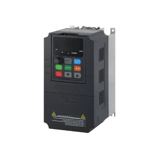
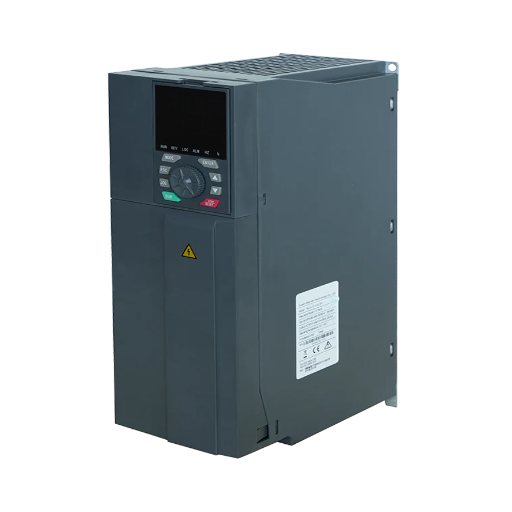
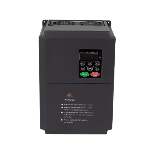
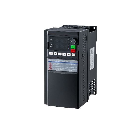
Ready to Get Your VFD Solution?
Whether you need a single drive or a complete system, we have the VFD products and engineering support to ensure your project's success.

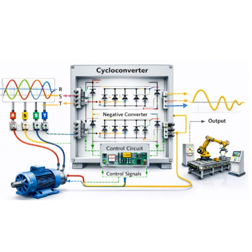
The cycloconverter vs matrix converter question is usually framed as a choice between two alternatives. It is not.
Both are direct AC-to-AC converters with no DC link, but each is capped by a different quantity. A cycloconverter’s output frequency cannot exceed roughly one third of its input frequency, which is 16.7 Hz on a 50 Hz supply. A matrix converter’s output frequency is free. Its output voltage is not: 50 percent with plain modulation, and 87 percent only with a harmonic-injection scheme that costs common-mode voltage at the motor.
That sounds abstract until it meets a project. Ilse Bergmann, an engineer at a copper concentrator, was asked to consider a matrix converter for a 12 MW mill.
A week of datasheets passed before anyone noticed the obvious problem. The largest matrix converter drive the team could find in commercial production was rated at 5 MW. The mill was always going to be a cycloconverter or a standard drive.
People ask for a cycloconverter vs matrix converter comparison because the two are taught together. Both appear in the same chapter of every power electronics text, both avoid the DC link, and both get called “direct.” The resemblance stops at the schematic.
Three things follow for the cycloconverter vs matrix converter decision: the ceilings as numbers you can check, the reason each device exists, and a five-question test.
Key Takeaways
- A cycloconverter is limited by output frequency, about one third of the input, which is 16.7 Hz on a 50 Hz supply.
- A matrix converter is limited by output voltage: 0.5 of the input with plain modulation, up to 0.866 with third-harmonic injection.
- The 0.866 figure is bought with common-mode voltage at the motor terminals, which is why the plain 0.5 still matters.
- The two never compete at the same duty: a cycloconverter drives a 28 MW mill, while the largest commercial matrix converter drive we could identify is rated at about 5 MW.
- Below a few megawatts at ordinary speeds, a standard PWM drive with a DC link is cheaper, faster to replace, and good enough.
Strip away the switch diagrams and the difference is two numbers. One device is limited by how fast it can build the output wave, the other by how much voltage it can pass through.
| Cycloconverter | Matrix converter | Standard PWM drive | |
|---|---|---|---|
| Power devices | Thyristors, natural commutation | 9 bidirectional switches, forced commutation | 6 IGBTs plus a diode rectifier |
| Output frequency | Below about 1/3 of input | Independent of input | Independent of input |
| Voltage transfer | Built from segments of the input wave | 0.5 plain, up to 0.866 with third-harmonic injection | Set by the DC link |
| Power range | Tens of megawatts | About 5 MW in the largest product we could confirm | Several megawatts at low voltage |
| Input current | Rich in low-order harmonics | Near-sinusoidal, no filter required | Not sinusoidal without a filter |
| Regeneration | Inherent | Inherent | Active front end or braking unit |
| Typical duty | Very slow, high-torque machines | Regenerative duty under 5 MW | Everything else |
The third column is there for a reason. Most engineers searching for a cycloconverter vs matrix converter comparison want a drive between 100 kW and 2 MW. The honest answer at that size is usually the column neither of the other two names. If the vocabulary is still unfamiliar, our guide to what a frequency converter is covers it without the comparison.
A direct AC-AC converter builds its output from the input waveform without storing energy in between. There is no rectifier charging a capacitor, no DC bus, and no second conversion stage. Switching devices connect the input lines to the output lines in a pattern that produces the wave you asked for. That much is the only common ground in a cycloconverter vs matrix converter comparison.
The DC link that a direct AC-AC converter avoids is not a design flaw left in by cautious engineers. It is a buffer, and the buffer buys three things. It decouples output voltage from input voltage, so the drive can hold a constant volts-per-hertz ratio as frequency falls. It stores enough energy to ride through a short supply dip.
And it lets the inverter use cheap, well-understood devices with a mature supply chain. Both sides of the line trade all of that away. What a cycloconverter vs matrix converter design gets back is efficiency, a smaller cabinet, and regeneration without extra hardware.
Whether that trade is worth making is the real dividing line. It is the same line that separates direct from indirect conversion in our AC frequency converter guide.
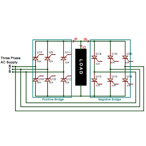
A cycloconverter is a set of thyristor bridges, arranged in positive and negative groups, that switch segments of the input sine wave into the output. The thyristors turn off when the supply current falls to zero. That is what natural commutation means: the mains does the switching work, so the converter needs no gate drive on its power devices.
The topology predates the IGBT by decades and still drives a 28 MW mill. Cheap per megawatt, rugged, and limited in exactly one dimension.
The output is assembled from pieces of the input. To produce a recognisable sine at the output, the converter needs enough input cycles to slice up. Below about three to one, the output becomes a staircase and the low-order harmonics dominate.
That ceiling is the first number in a cycloconverter vs matrix converter comparison, and it is the one that rules the device in or out. On a 50 Hz supply, a third is 16.7 Hz and a half is 25 Hz. On a 60 Hz supply, the figures are 20 Hz and 30 Hz.
That is the entire application envelope. A two-pole machine at 16.7 Hz turns at 1,000 rpm. A 40-pole machine at the same frequency turns at 50 rpm, and a mill turning at a few revolutions per minute is not limited by 16 Hz at all. The ceiling only binds if your machine needs to be fast.
Gearless mill drives are the flagship. ABB’s own brochure describes the arrangement: “The gearless motor is fed by a cycloconverter which has a rated output frequency of around 5 Hz for the GMD drive. The fuseless cycloconverter is connected to the MV network through three special cycloconverter transformers.”
The power is the other half of the story. International Mining reported in October 2009 on the Toromocho project: “One system will be installed on a 12.2 m SAG mill with a power of 28 MW. The SAG mill will be equipped with the new ABB 18-pulse cycloconverter. The other two GMD systems will be installed on 8.5 m ball mills rated with a power of 22 MW.”
The same supplement puts the economic threshold at “about 10 MW.” Ship propulsion and hoists use the same property for the same reason. High torque at low speed is the requirement, and a 16 Hz ceiling is no constraint when the drum never needs to turn quickly. A cycloconverter drive in a marine application is chosen for the duty, not in spite of the limit.
Efficiency in a cycloconverter vs matrix converter argument is closer than the topology suggests, but the claim comes with a caveat. The same source notes that “cycloconverters are slightly better than Voltage Source or Line Commutated Inverters.” It then adds that “the whole drive system has to be evaluated because the output of cycloconverters tends to have more harmonic content.” Read that twice before quoting the first half.
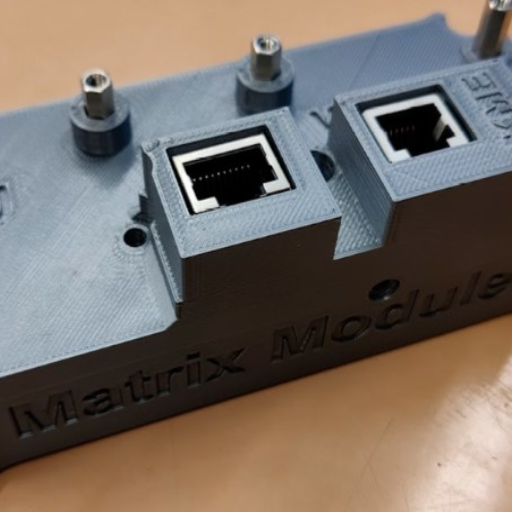
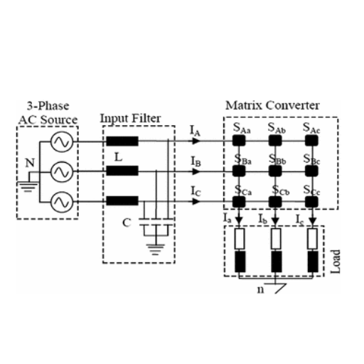
A matrix converter has no energy store to fall back on, so it builds the output wave from the input continuously. The three-phase version needs nine bidirectional switches, as Jeff Shepard wrote in EV Engineering: “A three-phase to three-phase matrix converter requires nine bidirectional switches.” In practice each switch is two IGBTs with anti-parallel diodes, so a 400 kW unit carries roughly 18 devices where a PWM drive of the same rating carries six.
That device count is the first thing a cycloconverter vs matrix converter comparison notices, and the least useful. The switches must never short two input phases together, and must never open an output phase while current is flowing. Neither error can be corrected after the fact, so the controller sequences every transition through a multi-step commutation pattern. Shepard spells out the consequence of getting it wrong: “otherwise, a catastrophic fault can occur, such as a short circuit on the input.”
That is the engineering cost. The matrix converter buys efficiency and a sinusoidal input current with a more demanding controller and a protection scheme that has less margin for error than a DC-link drive.
Here is where most cycloconverter vs matrix converter comparisons go quiet. The familiar 87 percent is quoted as if it were a property of the device. It is a property of the cleverest modulation scheme demonstrated on it.
| Modulation scheme | Maximum voltage transfer ratio | What it costs |
|---|---|---|
| Plain sinusoidal (Venturini, 1980) | 0.5 | Nothing beyond the ceiling itself |
| Input third-harmonic injection | 0.75 | Common-mode voltage on the input side |
| Input and output third-harmonic injection, or space-vector modulation (Alesina and Venturini, 1988) | 0.866 | Common-mode voltage at the motor terminals |
The plain scheme is severe. Half the input voltage is a hard arithmetic fact, because the output peak must fit inside the input envelope. The third-harmonic schemes work by reshaping that envelope, which is how they extract more. The extra they extract is real, and so is the voltage they leave behind.
Common-mode voltage is not a footnote. Matrix converters produce a high dv/dt common-mode waveform, which charges the rotor through parasitic capacitance and appears as shaft voltage and bearing current. The literature on eliminating it is large, and every technique that removes it gives back part of the ratio the injection was there to win.
Almost every cycloconverter vs matrix converter article reads as if matrix converters were a textbook concept. One is in production. Yaskawa’s FSDrive-MX1S, by its own product literature, holds “a power conversion efficiency of approximately 98 percent.” It keeps a power factor of 0.95, needs no harmonic filter, regenerates power, rides through a two-second supply loss, and has no electrolytic capacitor.
Its output is near-sinusoidal, so existing motors and cables can be reused. The largest unit in the range is specified at 6,000 kVA, which corresponds to a motor of roughly 5 MW. That is a catalogue ceiling, not a law of physics, and it should be confirmed against current ordering tables.
Tobias Lindqvist specified a 2 MW regenerative duty for a downhill conveyor at a paper mill. The matrix converter quoted at 98 percent efficiency and no input filter looked expensive beside a standard drive, until the harmonic filter, braking resistor and extra cabinet width were priced in. The matrix converter won on floor area, not on efficiency. The two quotes landed within 4 percent once the panel was built.
The ordinary variable frequency drive is a rectifier, a DC link and an inverter. It is the boring answer to the cycloconverter vs matrix converter comparison, and usually the right one.
What the DC link buys is availability. A 400 kW PWM drive is a catalogue item from a dozen manufacturers, with standard protection, standard communications and a supply chain that can land a replacement in days. It tolerates voltage sag, accepts a wider input range, and its control software has been debugged on more installations than any topology here.
What it costs is the capacitor. The electrolytic bank in the DC link has a finite life, and heat is what ends it. It also costs cabinet space, and its input current is not sinusoidal unless a reactor or filter is added. In any cycloconverter vs matrix converter budget, those harmonic current limits are the line item that surprises people.
A static frequency converter sits on the same indirect side of the line. It is the right reference point when the duty is fixed-frequency rather than variable-speed.
Most cycloconverter vs matrix converter tables mix sourced figures with remembered ones. This one separates them.
| Claim | Cycloconverter | Matrix converter drive | PWM drive |
|---|---|---|---|
| Output frequency | Around 5 Hz in a mill drive; textbook limit about 1/3 of input | Independent of input, per the MX1S specification | Independent of input |
| Highest power confirmed | 28 MW, one 2009 project | 6,000 kVA, roughly 5 MW, MX1S top of range | Not established here |
| Voltage transfer | Synthesised, no fixed ratio | 0.5 to 0.866 depending on modulation | Not limited by topology |
| Input current | More harmonic content, per the same source | Near-sinusoidal, no filter required, per Yaskawa | Not sinusoidal without a filter |
| Regeneration | Inherent | Inherent | Active front end or braking unit |
These rows are single-product or single-project facts, not laws. The 28 MW is one SAG mill in one report. The 5 MW is one product line.
Read the table as evidence of where a cycloconverter drive and a matrix converter drive have actually been built, not as a boundary.
Five questions settle most cycloconverter vs matrix converter cases. Stop at the first one that answers itself.
Above 30 MW, or above 690 V, this article stops being useful. The assessment changes, and sending us the load and the speed beats another table.
A cycloconverter uses thyristors and natural commutation to build a low output frequency from segments of the input wave, and is limited to about one third of the input frequency. A matrix converter uses nine bidirectional switches with forced commutation, and is limited by voltage transfer rather than frequency.
Above 5 MW, no. The largest commercial matrix converter drive we could identify is rated at 6,000 kVA, roughly 5 MW. Cycloconverters are built at 28 MW. Below that line, the duty decides, not the topology.
Four reasons. Nine bidirectional switches instead of six IGBTs and a commutation sequence that cannot tolerate an error. Protection must act before a short circuit develops, and the power ceiling is set by the devices available.
About one third of the input frequency in normal designs. That is 16.7 Hz on a 50 Hz supply and 20 Hz on a 60 Hz supply. Some designs push toward a half, at the cost of waveform quality.
No. That is the source of both its efficiency and its protection problem. Without an energy store, there is nothing to ride through a fault or a supply dip, so the controller and the protection scheme carry the whole burden.
The cycloconverter vs matrix converter efficiency comparison is not meaningful, because the two are never tested at the same duty. Yaskawa quotes about 98 percent for the MX1S. International Mining reports that cycloconverters are “slightly better than Voltage Source or Line Commutated Inverters” while noting their higher harmonic content. Neither figure transfers to the other device.
Two ceilings, one conclusion. A cycloconverter is limited by frequency, roughly a third of the input. A matrix converter is limited by voltage: 50 percent of the input plain, 87 percent with the clever modulation switched on.
Because the limits are different quantities, the cycloconverter vs matrix converter choice almost never arises on the same project. One belongs to a 28 MW mill turning at a few revolutions per minute. The other belongs to a regenerative conveyor or a downhill load in the low single-digit megawatts, where a near-sinusoidal input current and no filter are worth paying for.
The third answer deserves the last word in any cycloconverter vs matrix converter discussion. Below a few megawatts at ordinary speeds, a standard PWM drive is cheaper, more available and easier to protect. An article that says otherwise is selling something.
Start with the duty. Tell us the machine, the speed range and the power, and we will tell you which of the three is the honest answer. Send us the application →