Ready to Get Your VFD Solution?
Whether you need a single drive or a complete system, we have the VFD products and engineering support to ensure your project's success.

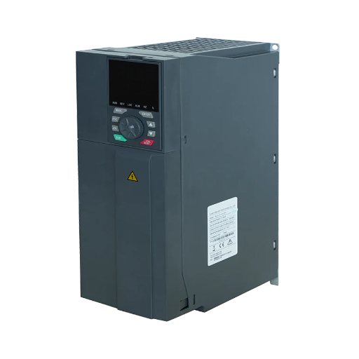
Vector variable frequency drive specs are not comparable. Compare speed accuracy bases, low-speed torque, and encoder needs with this buyer's checklist.
A vector variable frequency drive is a VFD that controls motor flux and torque separately, giving it better low-speed torque and speed regulation than basic V/f control. The label doesn’t tell you whether the drive uses sensorless vector control, closed-loop vector, or direct torque control, and that difference decides whether it fits your load.
Two drives can both print “vector” on the cover and publish speed accuracy figures that differ by a factor of five. One figure may refer to rated speed, another to maximum frequency, and a third to nominal slip. The quotes look comparable. The performance is not.
This guide covers industrial vector variable frequency drives for AC motors, not vector graphics or CNC drives. It gives you four numbers, a data sheet, eight questions, and an acceptance test. If you already have quotes, start with our vector VFD range and run the four-number test on every page.
Key Takeaways
- A vector variable frequency drive is an umbrella label for sensorless vector, closed-loop vector, and direct torque control. Ask which one the quote includes.
- Published speed accuracy is not comparable until you know the base. ABB cites ±0.1% sensorless, WEG cites 0.5% of rated speed, and Yaskawa cites ±0.2% of maximum frequency.
- Sensorless vector can produce full torque at zero speed on some drives, but sustained braking torque near zero speed needs an encoder.
- Overload is a time-current pair. 180% for 3 seconds and 150% for 60 seconds solve different starting problems.
- Test at the shaft before sign-off: low-speed torque, speed regulation at 10%, 50%, and 100%, and encoder direction.
A standard V/f drive holds a fixed voltage-to-frequency ratio and lets slip vary. That is enough for a fan or pump, but not when the load needs high torque at low speed or speed must hold while torque changes.
Vector control splits motor current into flux-producing and torque-producing components. The drive estimates or measures rotor flux position, then adjusts the output so each component follows its reference. That is field-oriented control, and it lets a vector drive hold torque at low speed where V/f cannot.
Two drives can use the same method and still differ in overload rating, encoder interface, auto-tune range, carrier frequency, and ambient rating. A quote that says only “vector” tells you little.
For the modes themselves, see the four VFD control modes compared. This article stays on the buying decision.
Ask for each number with its base, test condition, and motor.
Starting torque decides whether the machine can break away. Yaskawa states open-loop vector produces 200% of rated torque at 0.3 Hz, while closed-loop vector produces 200% at 0 rpm. At 0.3 Hz the field still rotates; at 0 rpm the shaft is stopped.
The YC-5000 publishes 200% at 0.5 Hz. Treat that as a rotating-field figure, not a standstill guarantee. For zero-speed hold, ask for a standstill figure and an encoder.
A percentage means nothing until you know its base. The table puts three published examples side by side.
| Source | Control mode | Published figure | Base and condition |
|---|---|---|---|
| ABB DTC white paper | Sensorless DTC | ±0.1% static speed accuracy | Typical, depending on motor size |
| ABB DTC white paper | DTC with encoder | ±0.01% | Standard 1,024 pulses/rev encoder |
| WEG CFW500 manual | Sensorless vector | 0.5% | Of rated speed, 1:100 range |
| WEG CFW500 manual | Vector with encoder | 0.1% | Of rated speed, 1:100 range |
| Yaskawa control-method article | Open-loop vector | ±0.2% | Of maximum frequency, 1:200 range |
| Yaskawa control-method article | Closed-loop vector | 200% torque at 0 rpm | Encoder required |
The numbers aren’t interchangeable. Compare the same base, motor, and test.
Torque response is how fast the drive changes torque after a command or load step. ABB publishes 1 to 5 milliseconds for a 100% torque step on its DTC drives, which matters for a winder or test stand. It isn’t speed response: a drive can change torque in milliseconds and still take seconds to recover speed on a high-inertia load.
At 60 Hz, 1:100 reaches 0.6 Hz, 1:200 reaches 0.3 Hz, and 1:40 reaches 1.5 Hz. Ask for the minimum continuous speed under load, not just the ratio. A drive may hold 1 Hz unloaded and lose control at 3 Hz with a full conveyor.
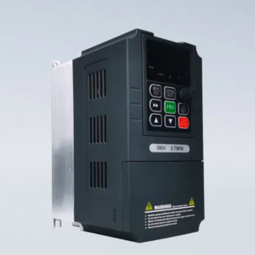
The same performance can produce different percentages depending on the denominator. WEG uses percent of rated speed, Yaskawa uses percent of maximum frequency, and some drives use percent of nominal slip, which can look smaller at full load.
At 1,750 rpm, 0.5% is 8.75 rpm and 0.1% is 1.75 rpm, a real difference at the shaft. But 0.5% of rated speed may be tighter than 0.2% of maximum frequency if maximum frequency is higher. You can’t tell from the percentage alone.
“Typical” is not a guarantee. ABB labels its ±0.1% sensorless figure as typical and says it depends on motor size. Yaskawa describes control methods, not a guaranteed envelope for every motor. Ask for the guaranteed value at your motor, load, and site conditions; if the answer is “typical”, put the test in the acceptance protocol.
An encoder changes both the figure and the cost. ABB publishes ±0.01% with a 1,024 pulses/rev encoder; WEG publishes 0.1% with an encoder. Those differ by a factor of ten even though both use feedback. Resolution, speed loop, and test conditions all matter.
Priya, a system integrator in Pune, compared three conveyor quotes that all claimed 0.5% accuracy. One meant 0.5% of rated speed, one 0.5% of maximum frequency, and one was valid only above 10 Hz. At 8 Hz creep, the error differed by more than the price gap. She rewrote the spec to require the base, test speed, and load condition. Only then were the quotes comparable.
For the accuracy bands, see what speed accuracy figures mean.
Sensorless vector has improved enough that many applications no longer need an encoder. ABB states that no speed or position feedback is needed in 95% of applications, and its DTC drives provide 100% torque down to zero speed without feedback.
The limit is not torque but holding or braking near zero speed for an extended time. ABB notes that a speed or position sensor is required if braking torque is needed close to zero speed for more than a few seconds. That is the boundary for hoists, unwinders, and back-driven loads.
Specify closed-loop vector when the application includes:
The encoder adds mounting, coupling, cable, interface card, and commissioning time. Price the whole package, not the encoder alone.
Tomas, a paper mill maintenance engineer, ran a winder in sensorless vector. At normal speed it held tension. Below about 2 Hz at thread-up, the drive lost its speed estimate, the tension controller hunted, and the sheet broke twice a shift. An encoder and PG card fixed it. The drive had been sized correctly; sensorless control couldn’t hold that condition.
The YC-5000 includes sensorless vector as standard and offers closed-loop vector with an optional PG card for ±0.01% speed regulation. The PG card and encoder are options, not built-in features. Start with the YC-5000 low-voltage VFD if you need that path.
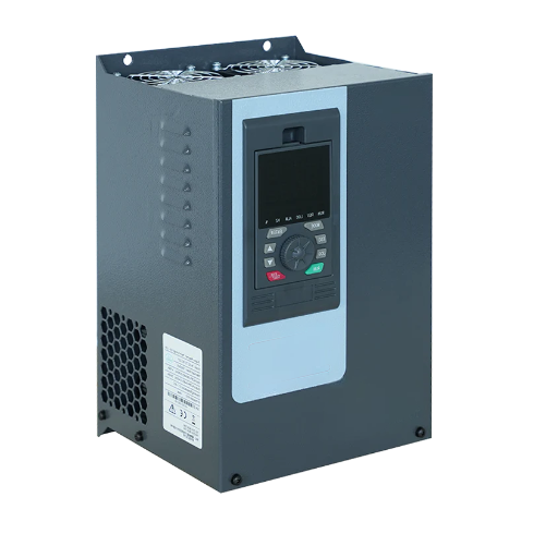
A supplier can’t size a vector drive from a kW rating. The nameplate gives current; the load gives duty.
| Category | Data to collect | Why it matters |
|---|---|---|
| Motor | kW or HP, voltage, full-load current, rated speed, poles, service factor, insulation class | Sets the drive current rating and motor model |
| Motor duty | Inverter-duty or standard, cooling method, maximum speed | Sets low-speed torque and cable limits |
| Load | Constant or variable torque, breakaway torque, inertia, starts per hour | Sets overload and acceleration rating |
| Process | Minimum and maximum speed, accuracy, torque response, encoder needed | Sets control mode and feedback |
| Environment | Ambient temperature, altitude, enclosure, dust or moisture | Sets derating and IP rating |
| Installation | Cable length, grounding, harmonics, communication protocol | Sets filters, reactors, and I/O |
Overload is a current percentage and a time. The YC-5000 publishes 150% for 60 seconds and 180% for 10 seconds; the YC-1610 publishes 150% for 60 seconds and 180% for 3 seconds. Those are not the same capability even though both mention 180%. Match the pair to the load profile, not the biggest number.
The YC-5000 publishes -10°C to +50°C; the YC-1800 publishes up to 3,000 m without derating. Above those limits, derate or change the enclosure. A higher carrier frequency reduces noise and ripple but increases switching loss and can force a derating; ask for the derated current at your carrier frequency. Long cables add capacitance and voltage reflection, so ask about a dV/dt filter or output reactor if the motor is far from the drive.
A procurement team bought a vector drive because the headline said 180% overload. The conveyor needed 150% for about 60 seconds on a cold start. The 180% rating lasted 3 seconds, then the drive tripped. Production lost 40 minutes a day for a week before the drive was replaced with a 150% for 60 seconds model. The peak number was correct. The duration was wrong.
A vector drive quotation should answer more than the power rating. Send the data sheet and ask these eight questions in writing.
If a supplier can’t answer questions 2, 3, and 5 in writing, the quote is a brochure, not a specification.
The acceptance test is where a quote becomes a fact. Run it with the real motor, load, and cable. Record every result.
A drive that meets the quote on paper but not at the shaft is not a successful commissioning. The report is your evidence if the supplier later claims the application was outside the specification.
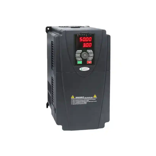
Vector control isn’t automatically right. It carries a premium, requires motor data and tuning, and can be wasted on a load that does not need it.
For the full framework, see when vector control is worth the premium.
A vector variable frequency drive is a VFD that controls motor flux and torque separately rather than holding a fixed voltage-to-frequency ratio, which improves low-speed torque and speed regulation. The label covers sensorless vector, closed-loop vector, and direct torque control, so the mode matters.
In practice, yes. Vector control VFD, vector control drive, and vector variable frequency drive are different names for the same product category. The important difference is the control method and the feedback hardware inside the drive.
Not always. Sensorless vector control estimates rotor speed and flux from voltage and current, and ABB states that no encoder is needed in 95% of applications. An encoder is required when the load must hold or brake near zero speed for more than a few seconds, when position accuracy matters, or when the process needs fast disturbance rejection.
Specify the accuracy at the shaft, at your minimum and maximum speed, under your load, and state the base. A figure such as 0.5% of rated speed, ±0.2% of maximum frequency, or 0.01% with an encoder is meaningful only with those conditions attached.
Yes, but it may be more capability than the application needs. Pumps and fans are variable-torque loads, and a V/f drive with slip compensation is often sufficient. A vector drive makes sense when the process needs low-speed torque, tight regulation, or a fast response to load changes.
It is worth it when the load needs low-speed torque, speed regulation under changing load, or feedback-based control. It is not worth it when a V/f drive already meets the process, when several motors share one drive, or when the real problem is mechanical.
A vector variable frequency drive is a control method, not a performance grade. The label covers sensorless vector, closed-loop vector, and direct torque control, and each publishes different numbers on different bases.
Use four numbers to compare quotes: starting torque at a stated frequency, speed accuracy at a stated base, torque response, and minimum continuous speed under load. Then ask eight questions, run the acceptance test, and record the results.
If you are comparing quotes now, send the motor and load data to our engineers and we will check the figures against the duty.