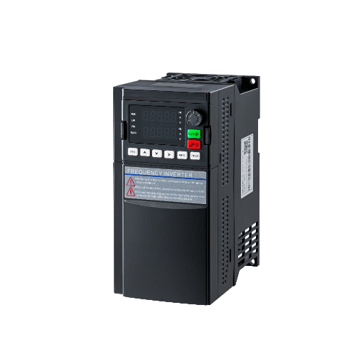
Ready to Get Your VFD Solution?
Whether you need a single drive or a complete system, we have the VFD products and engineering support to ensure your project's success.
Vector control low voltage drive is a drive that designs to control the motor flux as well as the torque, giving very good speed capabilities, high start-up torque, and controlled torque output across the span of speed. While basic V/f control keeps a known level fix of ratios of volts-per-hertz with no intelligence, vector control is popular for holding an approach of a formulated algorithm for reading the squirrel cage position and correcting the output of the inverter right realtime. For low-voltage applications–between 200 V out of 20% above 80to 230 V and at an upper end of 690 V–sensorless vector control handles nearly 80% of industrial applications with adequate regular performance and no need for vector feedback. Closed-loop vectors used with encoder information will be common in the business situations for ensuring better accuracy for positioning, zero-speed torque hold, and high dynamic web tension.
Ratchada was a maintenance engineer at plastics extrusion plant and located well outside of Bangkok; she learned the distinction the hard way. In March 2025, she replaced a new VFD on a 7.5 kW cooling fan and left the factory set Drive in V/f mode. The fan slowed to 15Hz with the load (tieing itself up), with this leading to jerk in speed of 8% and the extruder overhaets. She tried a sensorless vector, did a 60-sec auto-tune, and the fan now holds setpoint within 0.3% of difference from 5 to 60 Hz. The drive could do it right from the moment, with the difficulty being the selection of an inappropriate control mode for a load that required speed accuracy at low speeds.
If you are sizing or commissioning a low voltage VFD system and wondering whether V/f, sensorless vector, or encoder-based closed-loop vector is the right fit, this guide will give you a clear decision framework. You will learn exactly what each control mode does, which applications justify the cost premium, and how to commission vector control without getting lost in parameter menus.
Key Takeaways
- Vector control decouples flux and torque for precise speed and torque regulation; V/f simply scales voltage with frequency and ignores slip.
- Sensorless vector control covers roughly 80% of low-voltage industrial applications without requiring an encoder.
- Closed-loop vector with encoder feedback is only necessary for zero-speed torque hold, positioning accuracy under 0.1 degree, or high-dynamic tension control.
- V/f control is genuinely the right choice for fans, centrifugal pumps, and cost-sensitive retrofits where 2-3% speed accuracy is acceptable.
- Auto-tune failures are usually caused by incorrect motor nameplate data or long motor cables, not drive defects.

The fastest way to understand the V/f control vs vector control debate is to start with what vector control replaces.
V/f control, also called volts-per-hertz or scalar control, is the simplest method a VFD can use. It outputs voltage and frequency in a fixed ratio, assuming the motor will follow the commanded speed. The problem is that an induction motor never rotates exactly at synchronous speed. There is always slip, typically 1-3% at full load and much more at low speed or during heavy acceleration. V/f control does not measure or compensate for that slip in real time, so speed accuracy under load is usually in the ±2-3% range. For a rooftop fan or a centrifugal pump, that is often fine. For a conveyor feeding assembly stations, it is not.
Vector control solves this by treating the motor like a system with two separate inputs: flux current and torque current. Using a mathematical model of the motor (usually field-oriented control, or FOC), the drive measures stator current and voltage, calculates where the rotor flux is located, and adjusts the inverter PWM so the motor produces exactly the requested torque at exactly the requested speed. Speed accuracy improves to ±0.1-0.5% with sensorless vector, and to ±0.01% when an encoder provides true rotor position feedback.
Direct Torque Control (DTC) is a related variant used by some manufacturers. Instead of decomposing current into flux and torque components through coordinate transforms, DTC directly controls the stator flux and electromagnetic torque using hysteresis band controllers. The result is similar (fast torque response, good low-speed performance), but the implementation differs. For most low-voltage drives below 100 HP, FOC-based sensorless vector is the dominant architecture.
Low-voltage motors benefit disproportionately from vector control because they tend to run at wider speed ranges and lower inertias than large high-voltage machines. A 460V, 10 HP conveyor motor might need to crawl at 3 Hz while carrying a 50 kg pallet. That is exactly where V/f struggles and vector control shines.
For a broader introduction to selecting the right drive, see our complete guide to low voltage VFD selection.
Most modern low-voltage VFDs offer three control modes. Understanding where each one stops and the next one starts is the key to buying the right drive without overspending.
V/f control outputs a voltage proportional to frequency. The drive does not know what the motor shaft is actually doing; it simply trusts the motor to follow. Basic V/f is perfectly adequate for variable-torque loads like fans and centrifugal pumps, where the load itself eases off at low speed. Many drives also offer a slip-compensation enhancement, which estimates slip from output current and adds a small frequency correction. Slip compensation narrows speed accuracy to roughly ±1-2% without the cost or complexity of full vector control. Think of it as a halfway house that solves a large share of V/f complaints for a minimal price increase.
A sensorless vector control VFD builds a real-time motor model from stator voltage and current measurements. The drive estimates rotor flux position and speed mathematically, then decouples flux and torque commands. The result is speed accuracy of ±0.1-0.5% and full torque output from roughly 1 Hz upward. An auto-tune procedure is required so the drive can learn motor parameters such as stator resistance, leakage inductance, mutual inductance, and rotor time constant. Once tuned, sensorless vector can handle conveyors, mixers, positive-displacement pumps, and basic winders without any mechanical feedback device on the motor shaft.
An encoder feedback VFD adds an encoder to the motor shaft to report true rotor position and speed. Because the drive knows exactly where the rotor is, it can hold full torque at zero speed, achieve positioning accuracy better than 0.1 degree, and respond to load disturbances in milliseconds. The trade-off is cost and wiring complexity. An incremental encoder, cable, and interface card typically add $200-800 to a low-voltage drive system. Reserve closed-loop vector for hoists, cranes, high-accuracy indexing, web tension control, and servo-style positioning where sensorless vector cannot maintain stability.
For a deeper technical breakdown of the performance comparison, application scenarios and selection logic between low voltage and high voltage drives, see our Low Voltage Drive vs High Voltage Drive guide.
| Control Mode | Speed Accuracy | Min Speed for Torque | Encoder Needed | Relative Cost | Best Applications |
|---|---|---|---|---|---|
| V/f | ±2-3% | ~10-15 Hz | No | Baseline | Fans, centrifugal pumps |
| V/f + Slip Comp | ±1-2% | ~8-12 Hz | No | +5% | General-purpose pumps, simple conveyors |
| Sensorless Vector | ±0.1-0.5% | ~1 Hz | No | +15-25% | Conveyors, mixers, PD pumps, winders |
| Closed-Loop Vector | ±0.01% | 0 Hz (full torque) | Yes | +30-50% | Hoists, indexing, web tension, positioning |
If you are working with tight panel space and wondering how control mode choice interacts with drive size, our compact VFD selection guide covers physical sizing alongside performance.
Engineers love precision, but precision costs money. Vector-capable drives typically carry a 15-30% premium over V/f-only equivalents, and that premium is wasted if the application does not need it. Here are the cases where V/f is genuinely the right call.
Fans and centrifugal pumps are the classic examples. The affinity laws dictate that torque rises with the square of speed, so the load naturally lightens at low speed. A fan running at 30 Hz needs only 36% of its rated torque. V/f handles this comfortably, and the 2-3% speed accuracy of basic scalar control has no practical consequence on airflow in an HVAC or cooling-tower application.
Simple on/off or single-setpoint conveyors are also fine on V/f, provided they do not require accurate stopping or low-speed creep. If the conveyor runs at one fixed speed and simply needs to start and stop, scalar control is reliable and cost-effective.
Multi-motor setups, where one VFD runs several smaller motors wired in parallel, should almost always use V/f. Vector control assumes a single, known motor model. Running two or three mismatched motors on sensorless vector will confuse the drive estimator and produce erratic results.
Finally, cost-sensitive retrofits where speed accuracy beyond 2% is acceptable are perfect for basic V/f. If you are replacing a failed contactor starter with a VFD purely for soft-starting and a small amount of speed trimming, do not let a distributor upsell you to vector control. Buying vector capability for a rooftop AHU fan is usually wasted money.
That said, if your retrofit includes an energy savings target, the improved efficiency of modern IGBT drives (96-98%) often pays back the hardware cost faster than control mode selection does.
There is a point where V/f runs out of capability. Knowing exactly where that boundary lies will save you from commissioning headaches and production downtime.
Starting torque requirements are the first signal. A conveyor with heavy starting loads, such as a pallet loaded with steel parts, may need 150% rated torque at 1 Hz to break away from rest. V/f cannot deliver that because it does not know the rotor position at standstill. Sensorless vector can estimate the rotor flux and apply the correct current vector, giving reliable high starting torque without an encoder.
Speed regulation under varying load is the second signal. Mixers, positive-displacement pumps, and extruders see torque swings as material consistency changes. V/f will let speed droop when torque rises; sensorless vector senses the load change and compensates within milliseconds.
Low-speed operation is the third signal. Running a conveyor at 3 Hz for slow product feed, or a mixer at 5 Hz for gentle blending, is outside the comfort zone of scalar control. Sensorless vector maintains stable torque and accurate speed well below the threshold where V/f becomes unreliable.
VFD torque control applications, such as basic winders where you need to maintain tension but do not need servo-grade precision, are also well served by sensorless vector. The drive can switch from speed mode to torque mode and regulate current directly.
Rapid acceleration and deceleration of high-inertia loads push V/f to its limits. When a large flywheel or drum must change speed quickly, slip compensation cannot keep up. Sensorless vector adapts the current vector in real time, reducing the risk of overload trips and mechanical stress. For more on integrating drives into automated machinery, see our guide to VFD PLC integration for automation.
Sensorless vector requires an auto-tune procedure so the drive can populate its motor model with accurate parameters. There are two common types:
The parameters the drive learns are stator resistance, leakage inductance, mutual inductance, and rotor time constant. These values are specific to the motor, not the load, so you only need to re-tune if you change the motor or cable run.
When auto-tune fails, the cause is usually one of three things. First, the motor nameplate data entered into the drive is wrong. Double-check rated voltage, current, frequency, RPM, and power factor. Second, the motor cable is too long (over 100 meters for unshielded cable, over 50 meters for shielded). Long cables add capacitance that distorts the voltage waveform and corrupts the parameter measurement. Third, the motor has a brake or mechanical load that cannot spin freely during rotating auto-tune. Switch to stationary auto-tune, or disconnect the mechanical coupling.

Modern sensorless vector algorithms have closed the gap significantly. Many applications that once required encoders now run perfectly well in open-loop vector. But there are still hard boundaries where sensorless vector fails and encoder feedback becomes mandatory.
Zero-speed torque hold is the clearest boundary for closed loop vector control. A crane or hoist must hold a suspended load at standstill without mechanical brakes. Sensorless vector loses rotor flux estimation near 0 Hz; an encoder reports true position regardless of speed. If the application involves vertical axes, elevator-style motion, or any load that must not drift at rest, specify closed-loop vector from the start.
Positioning accuracy better than 0.1 degree is another boundary. Rotary indexing tables, packaging machines with precise cut-to-length registration, and servo replacements all need the rotor position resolution that only an encoder provides.
High-dynamic torque control with rapid disturbance rejection is the third boundary. Web tension lines in film, paper, or foil processing experience sudden tension spikes when material splices pass through. Sensorless vector may drift during the disturbance; encoder feedback locks the speed loop and allows the tension controller to recover in milliseconds.
The most common encoder for low-voltage drives is the incremental quadrature encoder with A, B, and Z channels. A 1024 PPR (pulses per revolution) encoder on a 4-pole motor gives the drive 4096 position updates per mechanical revolution when both edge transitions are counted. For applications that need absolute position after power loss (such as a crane that must know its elevation on restart), a single-turn or multi-turn absolute encoder is required.
Wiring matters. Encoder cables should be shielded twisted pair with differential line drivers (RS-422) to reject electrical noise from the inverter switching. Route the encoder cable separately from motor power cables, ground the shield at the drive end only, and never ground both ends (that creates ground loops). Poor encoder wiring is the single most common cause of closed-loop vector instability. For terminal wiring best practices, see our low voltage VFD installation and wiring guide.
Theory is useful, but the real test is what happens on the factory floor. Here are three actual low-voltage applications that illustrate when each control mode is the right choice.
A 10 HP, 460V centrifugal fan on a cooling tower in a Dallas data center runs 24/7 at varying speed to maintain condenser water temperature. The load is purely variable torque; at 30 Hz the fan needs only 36% of rated torque. The facility manager installed a basic V/f drive with slip compensation. Speed holds within 2% across the range, energy consumption dropped 42% versus damper control, and the total installed cost stayed low. Sensorless vector would have added $180 to the drive price with zero measurable benefit. This is honest V/f advocacy in action.
A 3 HP, 230V conveyor at an electronics assembly plant in Penang indexes product carriers between stations. The carriers weigh up to 50 kg, and the conveyor must crawl at 3 Hz for operator loading, then accelerate to 60 Hz for transfer. With V/f control, speed droop at 10 Hz under load was 4-6%, causing carriers to miss their indexing stops. The engineer switched to sensorless vector, ran a 90-second rotating auto-tune, and adjusted the speed regulator gain. Speed now holds within 0.3% at 3 Hz. No encoder was needed, and the line throughput improved 12% because carriers no longer required manual repositioning.
A 5 HP, 460V winder at a flexible packaging plant in Istanbul controls web tension for a blown-film line. The winder must maintain constant tension from a 1-meter diameter core to a 0.3-meter full roll, which means speed ranges from 50 Hz down to 8 Hz while torque ranges from 20% to 150%. The plant first tried sensorless vector. At low speed, flux estimation drifted, tension varied by ±15%, and film wrinkles ruined batches. They added a 1024 PPR incremental encoder with differential line driver, switched to closed-loop vector, and integrated the encoder feedback into the tension controller. Tension now holds within ±2% across the full roll diameter range. The $450 encoder investment eliminated thousands of dollars in scrap.

Commissioning sensorless vector control is straightforward if you prepare correctly. The following steps apply across most low-voltage drive brands, though parameter numbers will vary.
Gather the motor nameplate data: rated voltage, rated current, rated frequency, rated RPM, and power factor. Enter these into the drive’s motor parameters exactly as printed. Do not guess. A common mistake is entering the nameplate RPM as synchronous speed (1800 RPM for a 4-pole 60 Hz motor) rather than the actual rated speed (typically 1750-1770 RPM). That 30-50 RPM error corrupts the entire motor model.
Measure the motor cable length. If it exceeds 100 meters of unshielded cable or 50 meters of shielded cable, consider adding an output reactor or du/dt filter. Long cables create capacitive current that distorts voltage measurement and reduces auto-tune accuracy.
Disconnect the mechanical load if you plan to run a rotating auto-tune. A brake, gearbox, or coupled load prevents the motor from spinning freely and will cause the tune to abort or return incorrect values.
Start with stationary auto-tune if the load cannot be decoupled. The drive will lock the rotor, inject DC current, and measure resistance and inductance. This takes 10-30 seconds. You will hear a humming sound; this is normal.
If the load is disconnected, run rotating auto-tune next. The drive will accelerate the motor to roughly half of base speed, hold it for a few seconds, and decelerate. During this run, it measures no-load current and rotor time constant. The whole process takes 30-90 seconds depending on motor size and inertia.
After auto-tune completes, verify that the measured stator resistance and no-load current look reasonable. Stator resistance for a 10 HP, 460V motor is typically 0.5-2 ohms. No-load current is usually 30-50% of rated current. Values wildly outside these ranges suggest a wiring error or nameplate mistake.
For detailed wiring and panel-layout guidance, refer to our low voltage VFD installation and wiring guide.
Run a speed accuracy check at three points: low speed (10% of maximum), mid speed (50%), and high speed (100%). Use a handheld tachometer or the drive’s own speed estimate if you trust the encoderless reading. Compare actual speed to commanded speed. With sensorless vector, the error should be under 0.5% at all three points.
Run a load-step test. Apply a sudden load change (for example, engage a mechanical brake briefly or drop a load onto the conveyor) and watch the speed recovery. If speed dips more than 1-2% and takes more than 2 seconds to recover, increase the speed-loop proportional gain slightly and re-test.
If you are using torque control mode, verify torque linearity. Command 25%, 50%, 75%, and 100% torque and confirm the motor current scales proportionally. Non-linear torque response usually means the magnetizing current parameter is incorrect, which points back to a bad auto-tune.
If you are unsure about drive sizing for your motor, our guide on how to size a VFD on motor full-load amps walks through the calculation step by step.
V/f control maintains a fixed ratio of voltage to frequency and assumes the motor follows the commanded speed. It does not compensate for slip in real time, so speed accuracy is typically ±2-3%. Vector control builds a mathematical model of the motor, decouples flux and torque, and adjusts the inverter output in real time. This delivers speed accuracy of ±0.1-0.5% with sensorless vector, or ±0.01% with encoder feedback.
No. Sensorless vector control estimates rotor position from stator voltage and current measurements, and it works well for roughly 80% of low-voltage industrial applications. You only need an encoder for closed-loop vector, which is required for zero-speed torque hold, positioning accuracy under 0.1 degree, and high-dynamic web tension control.
V/f control is sufficient for fans, centrifugal pumps, simple on/off conveyors, multi-motor drives, and any application where 2-3% speed accuracy is acceptable. It is also the most cost-effective choice for basic retrofits. If your load is variable torque and does not require precise low-speed operation, V/f is the right choice.
Auto-tune measures motor electrical parameters so the drive can build an accurate motor model. Stationary auto-tune measures stator resistance and inductance. Rotating auto-tune adds no-load current and rotor time constant. These parameters let the drive calculate rotor flux position and separate flux current from torque current.
Yes, in most cases. The motor itself does not care which control algorithm the drive uses. You only need to ensure the motor is inverter-duty rated (NEMA MG1 Part 31) if you plan to run it at low speed for extended periods, where cooling from the shaft-mounted fan is reduced. Switching control modes is a parameter change and an auto-tune, not a hardware replacement.
Not directly. Energy savings in a VFD application come from reducing motor speed to match load demand, which both V/f and vector control can do. However, vector control can improve efficiency slightly by minimizing slip losses, because the drive actively maintains the optimal flux level rather than over-fluxing the motor. The main savings driver is still speed reduction, not control mode.
Choosing the right vector control low voltage drive is not about buying the most advanced option available. It is about matching the drive’s capability to the application’s real requirements.
V/f control handles fans, centrifugal pumps, and simple conveyors at the lowest cost. Sensorless vector control covers conveyors, mixers, positive-displacement pumps, and basic winders with ±0.1-0.5% speed accuracy and no encoder hardware. Closed-loop vector control with encoder feedback is reserved for the minority of applications that demand zero-speed torque hold, precise positioning, or high-dynamic tension control.
The decision framework is simple: start with the load characteristic, define your speed accuracy and torque requirements, and let the application guide the technology choice rather than the other way around.
If you need help selecting the right control mode for your next project, request application engineering support from our team. We will review your motor specifications, load profile, and performance targets, and recommend the most cost-effective solution for your application.


