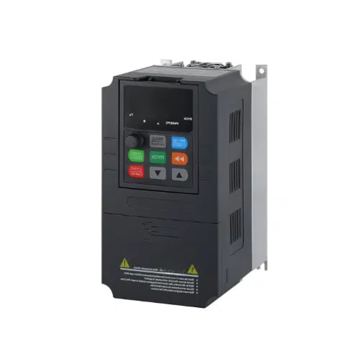
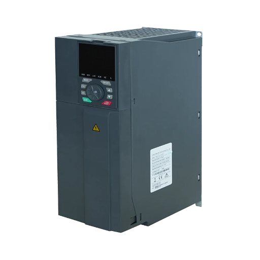
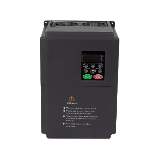
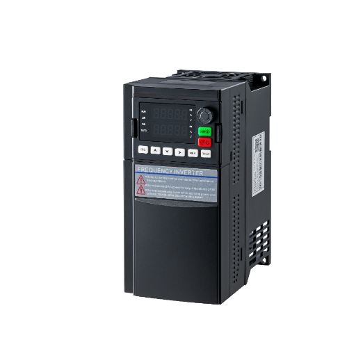
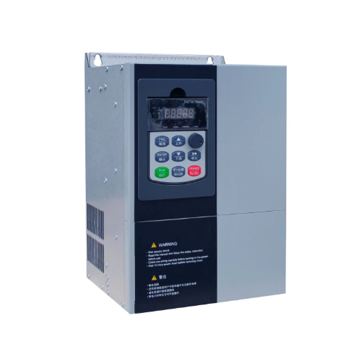
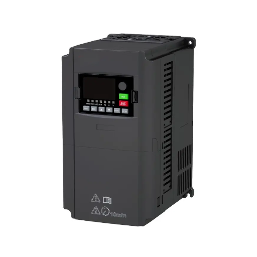
Ready to Get Your VFD Solution?
Whether you need a single drive or a complete system, we have the VFD products and engineering support to ensure your project's success.

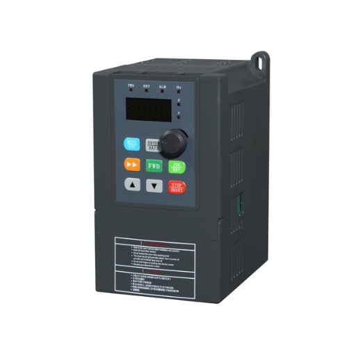
VFD speed control accuracy runs from ±1% with slip compensation to ±0.01% closed-loop. Learn what each figure measures and how to verify it at the shaft.
VFD speed control accuracy is not one number. A general-purpose drive in V/f mode with slip compensation holds speed within about ±1% of setpoint; without compensation the error follows motor slip, typically 2% to 3% and up to 5% at full load. Sensorless vector tightens that to roughly ±0.5%; closed-loop vector with an encoder reaches ±0.01% or better. Each figure is true only under the manufacturer’s conditions and base.
Marta, a process engineer at a film plant, specified a drive that promised ±0.01% speed regulation. The quote came back for the open-loop model. At 8% speed, tension wandered and the web wrinkled. The number belonged to a configuration the purchase order did not include.
You already know the brochure number and the machine number are different. This page explains what the percentage is measured against, why the motor and encoder often dominate the error, and how to verify it.
Key Takeaways
– ±0.01% is a closed-loop, encoder-referenced figure. It is not what an open-loop drive delivers.
– V/f accuracy follows motor slip; sensorless vector is about ±0.5%; closed-loop vector is about ±0.01%.
– The percentage needs a base: rated speed, maximum frequency, and motor slip differ.
– Resolution is not accuracy. A 0.01 Hz command step is finer than the drive’s real speed error.
– Verify at the shaft under load. In sensorless mode the displayed speed is an estimate.
Four numbers get called accuracy, and a datasheet rarely says which one it quotes.
| Number | What it tells you | A typical published figure | What it does not tell you |
|---|---|---|---|
| Frequency reference accuracy | How close the command is to the setpoint | ±0.01% of maximum frequency digital; ±0.1% to ±0.4% analog | How fast the shaft actually turns |
| Static speed regulation | How close shaft speed is to command at steady load | ±0.5% of rated speed sensorless; ±0.01% closed loop | How cleanly it recovers from a load step |
| Dynamic accuracy and bandwidth | How quickly and cleanly it recovers | 5–50 Hz standard; 100–200 Hz high performance | The steady-state error |
| Resolution and repeatability | The smallest command step, and whether the same command returns the same speed | 0.01 Hz command; 1024 to 8192 PPR encoder | Absolute accuracy against the process |
The first trap is the base. A percentage means nothing until you know what it is a percentage of.
Those statements describe very different machines. Convert every figure to rpm at the shaft before comparing drives.
Static accuracy is the error at steady load; dynamic accuracy is the recovery after a load step. ABB separates the two in its ACS880 data, quoting static accuracy in percent and dynamic accuracy in percent-seconds for a 100% torque step.
Your product also sees the motor, encoder, coupling, analog signal, and machine. A drive that regulates to ±0.01% at its terminals can still produce ±0.2% at the load if the coupling slips or the belt stretches.
The control method sets the ceiling. These figures come from WEG, Fuji, and ABB.
| Control mode | Feedback | Typical static accuracy | Speed range | Best fit | Watch-out |
|---|---|---|---|---|---|
| V/f, no slip compensation | None | Error follows motor slip, up to about 5% at full load on NEMA Design B | 1:20 to 1:40 | Fans, pumps, simple machinery | No correction for load or temperature |
| V/f with slip compensation | None | About 1% of rated speed | 1:20 | Pumps, simple conveyors | Model-based; drifts as the motor changes |
| Sensorless vector | Estimated from current and voltage | About ±0.5% of rated speed | 1:100 to 1:200 | Conveyors, mixers, extruders | Low-speed floor around 15 to 18 rpm on a 4-pole motor |
| Closed-loop vector | Encoder | About ±0.01% of rated speed | 1:1000 to 1:1500 | Winders, printing, multi-drive synchronization | Encoder, wiring, mounting, tuning |
A V/f drive sets frequency and voltage on a fixed curve and has no idea how fast the rotor is turning. The motor slips under load, and the drive does not correct for it.
NEMA Design B motors are allowed up to 5% slip at rated load, and typical designs run 2% to 3%. That is the order of the error from plain V/f at full load, shrinking at light load and growing at overload. WEG states that scalar control with slip compensation gives about 1% accuracy at rated speed with load variation. That is enough for a pump or a fan, not for a winder. For the frequency-to-speed relationship, see how a VFD turns frequency into motor speed.
Sensorless vector measures stator current and applied voltage, estimates rotor flux and speed, and closes a current loop around the motor model. WEG publishes 0.5% of rated speed over a 1:100 range; Fuji publishes ±0.5% of maximum frequency over 1:200. The catch is the bottom of the range. WEG recommends a minimum of about 15 rpm for a 50 Hz 4-pole motor and 18 rpm for a 60 Hz 4-pole motor, below which the drive switches to an I/f mode.
An encoder measures rotor position or speed directly, so slip, temperature, and load changes are no longer open-loop disturbances.
WEG publishes 0.01% of rated speed for vector control with an encoder over a 1:1000 range. Fuji publishes ±0.01% of maximum frequency with a sensor and a 1:1500 range. ABB publishes 0.01% of nominal speed closed loop. Mounting, coupling, and tuning still decide whether you get it.
Not sure which control mode your process needs? Compare VFD control modes →
Most field accuracy problems come from the other blocks in the stack.
An induction motor’s slip is not constant. It rises with load and changes with rotor resistance, which rises as the motor heats. WEG says the best self-tuning results come from a preheated motor. Learn the model cold, and it is slightly wrong all day.
Auto-tune is only as good as the model. Static tuning estimates parameters without rotating the shaft; rotational tuning spins the motor and estimates the mechanical time constant.
Both depend on correct nameplate data and a motor at a sensible temperature. Wrong nameplate data makes the accuracy claim meaningless. Our guide to VFD auto tuning covers both procedures.
The encoder is a mechanical device: shaft, coupling, mounting flange, cable. A coupling that slips under torque produces a speed error the drive cannot see, because the encoder reports its own speed, not the load’s.
Owen, a maintenance technician on a printing line, replaced a failed encoder with the same PPR but a different coupling. The drive reported the correct speed, yet the register drifted a few millimetres over a shift. A scope showed the coupling slipping under torque. The drive was accurate. The feedback was not.
The speed command is part of the chain. A digital reference from a keypad, PLC, or fieldbus is typically accurate to ±0.01% of maximum frequency. An analog reference is only as good as its source, resolution, and shielding.
A 12-bit input resolves about 2.4 mV per step over 0-10 V; a 14-bit about 0.6 mV. A noisy ground or a long unshielded cable can swamp either. WEG specifies 0.01% speed regulation with a 14-bit analog reference or a digital reference.
Backlash, belt stretch, chain slack, and torsional resonance sit after the motor shaft. The drive can hold the motor to ±0.01% while the load moves by 0.5% because the belt is stretching. If the process cares about where the product is rather than where the shaft is, a VFD may be regulating the wrong variable.
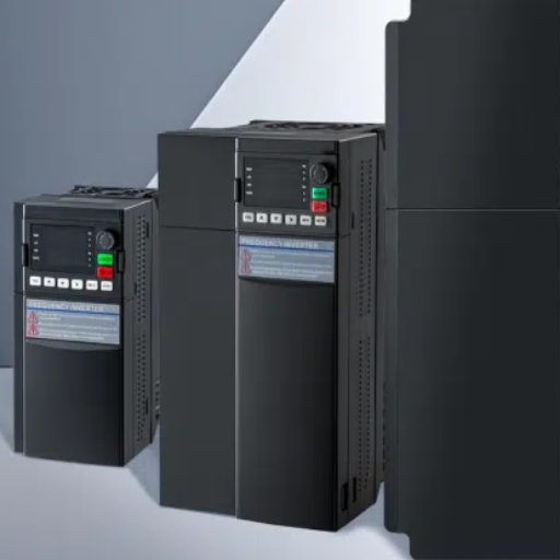
Four specifications get mixed together in buying conversations.
| Concept | Question it answers | Example |
|---|---|---|
| Frequency resolution | What is the smallest command step? | 0.01 Hz on a 4-pole 50 Hz motor is about 0.3 rpm |
| Accuracy | How close is actual speed to the command? | ±0.5% of 1,500 rpm is ±7.5 rpm |
| Repeatability | Does the same command return the same speed? | A drive can repeat within ±0.1% but sit 1% off absolute |
| Bandwidth | How fast does it respond? | A 10 Hz loop settles in roughly 50 ms |
On a 4-pole motor at 50 Hz, 0.01 Hz is about 0.3 rpm. That sounds precise. But a sensorless drive with ±0.5% accuracy at 1,500 rpm can be 7.5 rpm off, 25 times coarser than its command resolution. It does not correct slip, load error, or a bad motor model.
Encoder resolution works the same way. A 1024 PPR encoder at 1,500 rpm produces about 25,600 pulses per second.
At 1 rpm it produces about 17 pulses per second, so the drive must measure the period between pulses rather than count pulses in a fixed window. Industrial Monitor Direct recommends 2048-4096 PPR for medium bandwidth and 8192+ for high-bandwidth positioning. PPR is not accuracy either: a high-PPR encoder on a slipping coupling is still wrong.
Bandwidth is how fast the speed loop responds. Industrial Monitor Direct gives 5–50 Hz for standard drives and 100–200 Hz for high-performance drives, with the approximation bandwidth (Hz) ≈ 1 / (2 × settling time). A 10 Hz loop settles in about 50 ms; a 50 Hz loop in about 10 ms. Too much bandwidth on a high-inertia load causes oscillation and can trip the drive on overcurrent or overvoltage.
An encoder adds a device, a PG card, wiring, mounting, and commissioning time. Five questions usually settle the decision.
If the first answer is no, stop. Adding an encoder to a V/f drive does not buy much: Darwin Motion notes that V/f with an encoder reaches about ±0.03% of maximum frequency but does not improve dynamic response, and the PPR limits high-frequency operation. The benefit comes from closing the vector loop, not from the encoder alone.
Fans, pumps, simple conveyors, mixers, and many extruders run well on sensorless vector. The tolerance is usually ±0.5% to ±2%, and the load is predictable. For a retrofit with no free shaft end, or a drive running several motors, V/f or sensorless vector is enough.
If the process needs positioning, registration, electronic camming, or a bandwidth above what a VFD can deliver, a servo is the correct tool. A VFD with an encoder can hold speed to ±0.01%, but it is still a speed device. Our VFD versus servo drive guide covers the boundary.
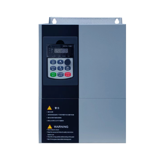
Shandong Electric’s YC-5000 low-voltage series publishes V/Hz, sensorless vector, and closed-loop vector control with a PG card option. The published figure is ±0.01% speed regulation with the PG card, 0.01 Hz frequency resolution, and 200% startup torque at 0.5 Hz. The YC-1610 and YC-1800 series cover V/F and sensorless vector duty; their pages do not publish a numeric speed accuracy, so specify the control mode and speed range.
Sizing a closed-loop drive for a winder, printing line, or synchronized conveyor? Explore the YC-5000 →
A specification without a test method is a wish. This procedure turns the datasheet number into something a commissioning engineer can accept or reject.
bandwidth ≈ 1 / (2 × settling time).Record the results in the commissioning report. It becomes the baseline for every future maintenance check.
A useful specification has four parts: control mode, feedback device, accuracy base, and test method. Here is a sentence that survives a tender:
“Static speed regulation shall be within ±0.5% of rated speed over a 1:100 speed range, from 10% to 100% load, measured at the motor shaft with an independent encoder.”
That sentence is testable. It names the base, range, load points, and instrument. A supplier who cannot meet it will say so before the order, not after.
Aisha, a plant engineer at a bottling plant, wrote a tender for six conveyor drives. Her first draft said “high accuracy, inverter duty”. Her second draft used the sentence above, with a 1:100 range and a shaft-mounted encoder.
Three suppliers quoted. The selected drive passed the test in one afternoon, and the commissioning report became the maintenance baseline. The difference was not a better drive. It was a number with a base and a test method.
Our VFD specification template includes the surrounding clauses for tenders and project manuals.
V/f with slip compensation holds within about ±1% of rated speed; plain V/f error follows motor slip, typically 2% to 3%. Sensorless vector holds about ±0.5% of rated speed, and closed-loop vector with an encoder about ±0.01%. Each figure applies only over the stated speed range and load conditions.
Not always. Sensorless vector is enough for fans, pumps, conveyors, mixers, and many extruders. Use an encoder when the process needs better than about ±0.5%, accuracy below roughly 5% speed, multi-motor synchronization, or torque control near zero speed.
No. 0.01 Hz is a command resolution. On a 4-pole 50 Hz motor it is about 0.3 rpm. A drive with ±0.5% accuracy at 1,500 rpm can be 7.5 rpm off, 25 times coarser than its resolution.
In open-loop V/f, the drive cannot see slip, so speed falls as load rises. In sensorless vector, the motor model may be wrong or the motor may be hot. In closed-loop vector, check the encoder coupling, wiring, and tuning before changing the drive.
A closed-loop vector drive with an encoder can hold zero speed and full torque. A sensorless drive loses authority at standstill, and a V/f drive cannot hold zero speed under load. If the load can pull the shaft backward, use an encoder.
Use a servo for position control, registration, electronic camming, or bandwidth above what a VFD can deliver. A closed-loop VFD can hold speed to ±0.01%, but it regulates the shaft, not the product position.
VFD speed control accuracy is a chain, not a badge. The control mode sets the ceiling, the motor’s slip and temperature move the actual speed, the encoder and wiring decide whether the loop can see the error, and the mechanical train decides whether the product benefits.
V/f is for fans and pumps, not registration. Sensorless vector is the workhorse for general machinery, with a low-speed floor. Closed-loop vector with a good encoder is the right answer when the process needs ±0.01%, and a servo is the right answer when the process needs position rather than speed.
When you write the specification, name the base, the speed range, the load points, and the instrument. A number with a base and a test method is a specification. A bare percentage is a hope.
Send us the process tolerance, the speed range, and the load profile. We will tell you which control mode and feedback option fits →