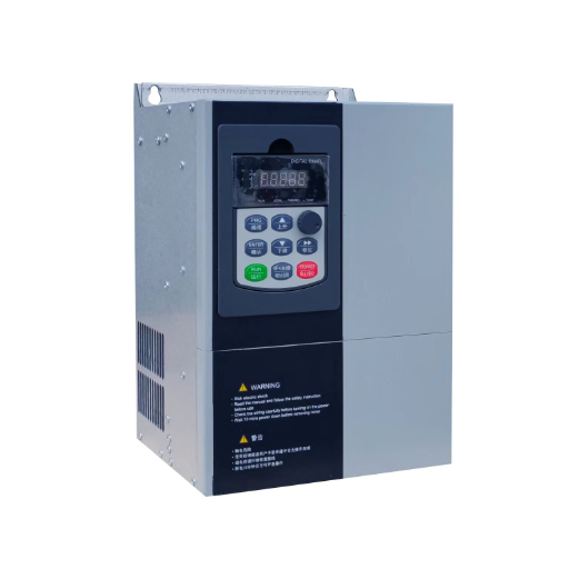
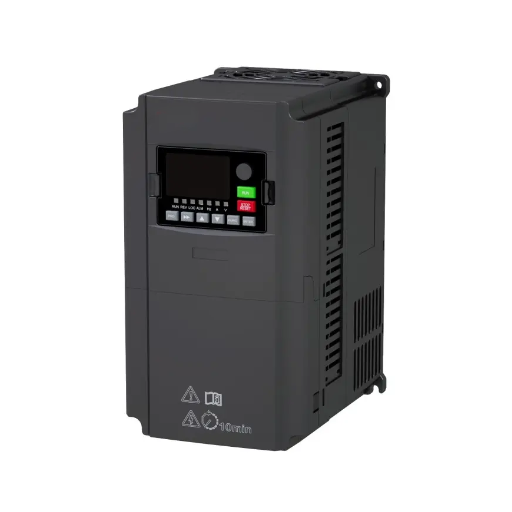
Ready to Get Your VFD Solution?
Whether you need a single drive or a complete system, we have the VFD products and engineering support to ensure your project's success.

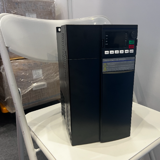
VFD torque at zero speed takes two things: a control mode that reaches zero, and a motor that can survive holding there. Here is how to check both of them.
A VFD can produce rated torque while the shaft is stopped, because motor torque comes from slip frequency rather than shaft speed. What limits the application is almost never the drive. It is whether the drive knows where the rotor is, and whether the motor survives holding.
Most engineers meet this from the wrong end. A supplier promises 200% torque at zero speed, the drive arrives, and the load still creeps.
In 2024, a maintenance engineer at a paper mill outside Dezhou, call them Xu Wei, chased a winder that settled about 15 mm on every stop. The drive was new, correctly sized and fitted with an encoder. It held the roll indefinitely. The settling came from the order of two events.
You already know a drive can hold a load. The useful question is what that costs and who pays. This page covers which control modes deliver it, why the motor gives out first, and the brake sequence that decides whether the load drops.
Key Takeaways
– Torque comes from slip frequency, not shaft speed. At standstill the drive turns the field slowly while the rotor sits still.
– Locked-rotor current is six to seven times rated, so the drive’s current limit sets what you can hold, not the motor’s torque curve.
– Sensorless vector has a low-speed floor. A drive can advertise f = 0, but Siemens restricts that mode to passive loads.
– The motor runs out before the drive does. A shaft-mounted fan moves no air at standstill.
– On a hoist the sequence is torque first then brake off, brake on then torque off. Reverse either and the load settles.
Tell us the load and the duty and we will say whether holding is realistic. Send us the application →
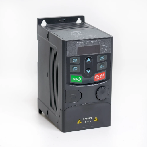
An induction motor has no magnets and no rotor winding connected to anything. Current appears in the rotor only because the stator field moves relative to it. That relative movement is slip frequency, and slip frequency is what makes torque.
A four-pole motor on 50 Hz has a synchronous speed of 1,500 rpm. At full load it runs at maybe 1,470 rpm. That 30 rpm gap is a slip of 1 Hz, and 1 Hz of relative motion is what pushes rated torque through the shaft.
Now stop the shaft and command the drive to 1.5 Hz. The field crawls round at 45 rpm. The rotor doesn’t move. The relative motion is still 1.5 Hz, so from the rotor’s point of view nothing has changed.
Same flux, same rotor current, same torque.
Zero speed means zero shaft speed, not zero output frequency.
At standstill with a 1.5 Hz field the motor is at 100% slip, the locked-rotor condition. Locked-rotor torque is typically 150% to 200% of rated, which is why a 200% holding claim is real. The problem is the current that comes with it.
Locked-rotor current is roughly six to seven times rated. A drive that applied full voltage at 1.5 Hz would trip on overcurrent or cook the motor, so it doesn’t.
Vector control splits stator current into a flux component and a torque component at right angles to it. At zero speed it holds flux at rated value, regulates torque to whatever the load needs, and sets the stator frequency to the matching slip. That is how a spec sheet says 200% at 0 Hz without lying.
This is also why an output of 0 Hz isn’t a hold. Zero hertz is direct current in the stator, making a stationary field, and a stationary field on a stationary rotor can’t produce controlled torque. It resists movement and heats the motor, and that’s all.
Siemens says its DC braking function “injects direct current into the motor, thus braking the motor”. DC injection is a brake, not a hold.
Drives have four answers, and the difference is what the drive knows about the rotor.
Four control modes, and the column buyers check last.
| Control mode | Torque at zero shaft speed | Encoder | What the manual calls it |
|---|---|---|---|
| V/Hz (scalar) | None usable. Torque boost helps at low speed, not at standstill | No | “V/f control”, “scalar control” |
| Open-loop (sensorless) vector | A floor, typically 1 to 3 Hz at useful torque. Some drives claim f = 0 with conditions | No | “Sensorless vector” |
| Direct torque control (DTC) | Close to zero without an encoder. Degrades under heavy overhauling load | No | “DTC”, “direct torque control” |
| Closed-loop vector | Rated torque, often 150% to 200%, at 0 Hz | Yes | “Closed-loop vector”, “encoder feedback” |
Every figure there is drive-specific. Two drives from the same brand can differ by a factor of two at the bottom of the range, so the only honest source is the manual for the model you’re buying.
V/Hz has no answer here. At 1.5 Hz the drive applies about 3% of rated voltage, but the volt drop across the stator resistance is a fixed few percent whatever the frequency. Almost all of it disappears into the resistance and the flux collapses. Torque boost adds voltage back on a curve, not a measurement.
DTC is the honest middle. It compares estimated flux and torque against hysteresis bands every switching cycle, with no modulator in the loop. It reaches much closer to zero than ordinary sensorless vector without an encoder, which is why it carries lifting work. It still loses authority at true standstill, because it’s still estimating.
Closed-loop vector control answers the question. The encoder reports rotor position directly, so there’s nothing to degrade, and the drive holds torque at zero speed as accurately as at rated speed.
If the tier decision is what you’re making, our guide to the high performance VFD tier covers what the extra cost buys, and general purpose versus high performance covers when the premium never pays back.
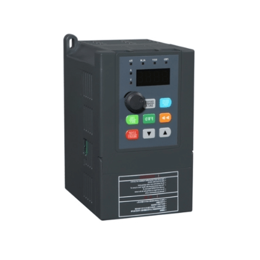
Sensorless vector control is the mode most drives ship with. It estimates flux and speed from measured currents and applied voltage, which works over most of the range and doesn’t work at the bottom.
At low speed the back-EMF the rotor induces is small, and the errors in the voltage measurement are not. Inverter dead time, device volt drops and motor parameter error all sit at a few percent of rated voltage. At rated speed that’s noise. At 1 Hz it’s the same order as the signal the estimator needs, which is the practical floor for open-loop vector.
A few drives advertise sensorless operation down to 0 Hz, and the claim is real inside a condition the datasheet won’t tell you about. Siemens names the setting “Sensorless control down to f = 0 (passive loads)” and defines it as “applications in which the load cannot produce a regenerative torque on startup and the motor comes to a standstill when pulses are inhibited (no overhauling load)”.
A fan, a pump and a horizontal conveyor are passive. A hoist, a winder, an inclined conveyor and a press are not. One sentence in a manual decides whether f = 0 is available to you.
A sensorless drive carries a model of your motor, and those values change with temperature. Copper resistance rises about 0.4% per °C, so a 60 °C winding rise makes the stator roughly 24% more resistive than it was cold.
Siemens states the consequence directly: below approximately 20% of rated speed, “torque accuracy depends primarily on whether thermal tracking of the stator resistance is carried out correctly”.
This explains a symptom that reads like a hardware fault. At a cement plant near Tangshan in 2023, a line operator, call them Ma Lin, watched a 22 kW motor hold a load at standstill every morning and trip on overload every afternoon. Same load, same setpoint, different result. The motor wasn’t overheating. The drive’s model was three hours out of date, so the torque estimate drifted and the winding cooked. A temperature sensor wired back to the drive ended it.
The drive’s torque claim and the motor’s thermal reality run on different clocks. A drive quoting 200% at 0 Hz means it can deliver that for seconds. A motor asked to hold rated torque for twenty minutes is answering a different question.
Most industrial motors are totally enclosed fan cooled. The fan is moulded into the end of the rotor and blows air over the frame, and airflow is proportional to shaft speed. That works because heat comes from current.
At standstill the fan is still. Cooling falls to natural convection off the frame, a small fraction of rated airflow, while the motor keeps making the same heat.
So the drive can hold. The motor may not survive holding.
Holding capability by frame type. Take the values from your motor’s data sheet, not from any table on the internet, including this one.
| Frame type | Cooling at standstill | Typical continuous holding | What to check |
|---|---|---|---|
| TEFC (shaft-mounted fan) | Frame surface only | A fraction of rated current, often 25% to 40% | The data sheet’s thermal limit at zero speed, and the ambient |
| TEBC or separately driven blower | Full, independent of speed | Up to rated, sometimes more | Blower supply, and whether it runs whenever the drive is enabled |
| Water or oil jacket | Full, independent of speed | Up to rated and above | Coolant flow, temperature and interlock |
If you need rated torque for minutes rather than seconds, you need independent cooling. A bigger drive doesn’t help, because the limit isn’t in the drive.
Duty cycle decides how much of that limit you can use. Holding for 30 seconds and holding for 20 minutes share a number but not a thermal answer, and the permitted holding current depends on duty and ambient temperature, not just load. Our guide to VFD duty cycles covers the S1 to S10 definitions.
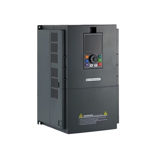
A mechanical brake holds the load overnight, and the drive hands it over without letting anything move. The handoff is what fails.
Four steps, in this order:
Hitachi’s hoist manual implements this as the Start of Run Motor Check, which “will check to make sure the motor has produced sufficient torque before releasing the motor brake”. It has a torque value, a check time, and a trip if the torque never arrives.
The mirror image, and the one people get wrong:
Step 4 is a delay you measure, not guess. A brake that takes 300 ms to seat lets the load move for 300 ms.
Xu Wei’s 15 mm came from the drive being disabled a fraction of a second before the brake had seated. The drive was doing its job. The sequence had the two events in the wrong order.
The same symptom has three causes, and they are distinguishable:
A fourth case looks like all three: a brake rated for static holding, used as a running brake. If the drive uses the brake to stop the load, the brake wears out and the symptom arrives with no parameter at fault.
The newest drives hold on the encoder at zero speed without setting the brake, so the brake only engages at a standstill. Hitachi calls this Load Float. For the application side, our crane and hoist VFD guide covers load cases and duty ratings.
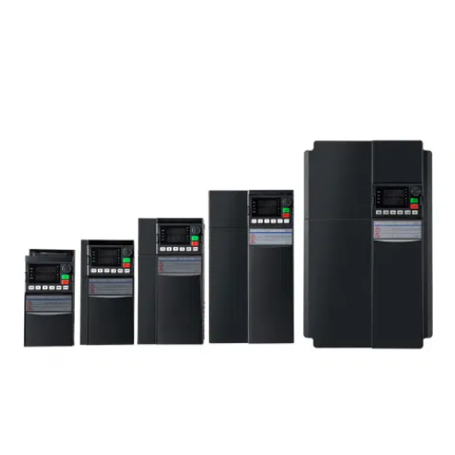
A VFD torque at zero speed claim lives or dies on six parameters. Names differ by brand. What they do doesn’t.
None of these are hidden. All six are in the manual’s parameter list, published before you buy. Our VFD parameter settings guide covers the wider set around them.
Send us the motor data sheet and the duty cycle and we will check the pair against these six settings. Ask for the check →
A motor can run at any speed down to zero, but how much torque it makes there depends on the control mode. V/Hz gives almost nothing at low speed, sensorless vector holds useful torque down to about 1 Hz, and closed-loop vector with an encoder holds rated torque at zero speed.
Yes, in two of the four modes. V/Hz loses torque because stator resistance dominates at low frequency and the flux collapses. Sensorless vector loses accuracy because the back-EMF it estimates from gets too small. Closed-loop vector doesn’t, because it measures rotor position instead of inferring it.
Because slip is zero there. An induction motor makes torque only when the rotor turns slower than the stator field. At synchronous speed the two move together, no current is induced, and torque falls away.
Sometimes. Drives with direct torque control reach close to zero without one, and some sensorless drives offer an f = 0 mode, usually restricted to passive loads with no overhauling torque. That rules out hoists and winches. If the load can pull the shaft backward, treat an encoder as required.
Because the shaft-mounted fan moves no air at standstill, so the motor loses most of its cooling while carrying holding current. A TEFC motor can typically hold only a fraction of rated current continuously. The fixes are a driven blower, a water jacket, a lower current, or a shorter hold.
It is the torque the drive produces to hold a suspended load before the brake releases and after it sets. Hoist drives treat it as a safety function, proving torque before releasing the brake and proving the brake before releasing torque. It needs closed-loop vector or DTC, and measured brake delays.
VFD torque at zero speed is two claims wearing one number. The drive’s: which control mode it has, and how much current it will push at standstill. The motor’s: how long it can carry that current with no fan turning. A page that sells you the first and stays quiet about the second has told you half the story.
Torque comes from slip, so a stopped shaft isn’t a stopped field. Locked-rotor current sets the ceiling. Sensorless control has a floor, and the drives claiming f = 0 mostly mean passive loads. The motor, not the drive, is usually what ends a long hold.
When you specify, ask for the duty cycle, the ambient, the frame type and the brake sequence with the torque figure. Those answers decide whether the brochure number survives its first week.
Send us the motor data sheet and the drive model. We will tell you which half is limiting you →