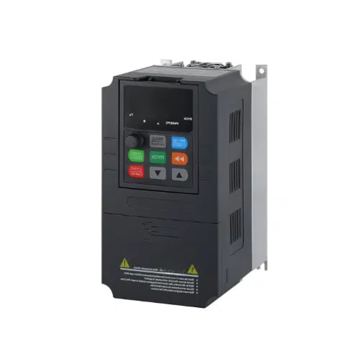
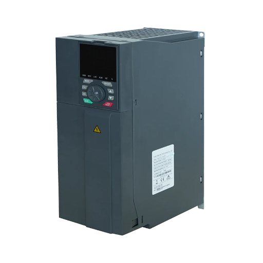
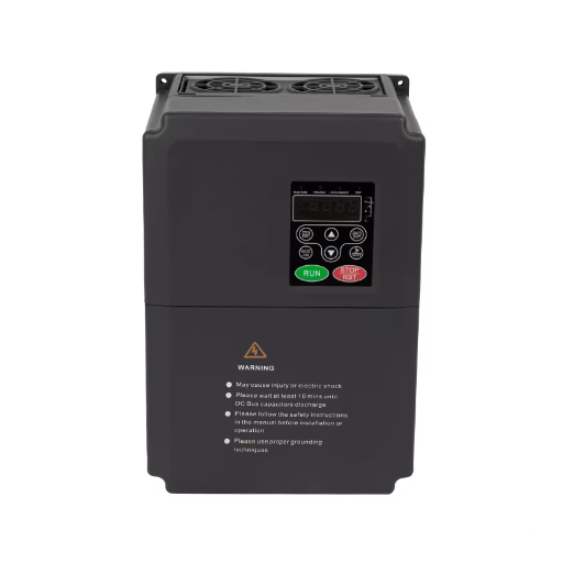
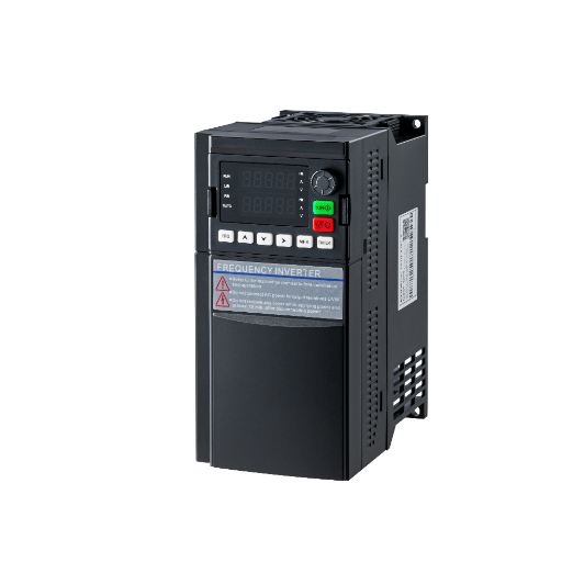
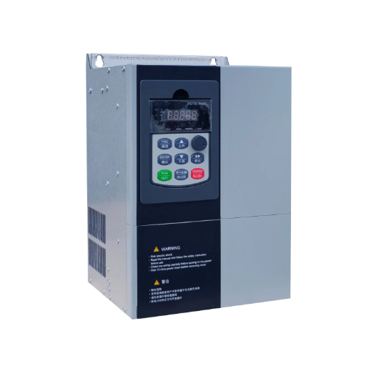
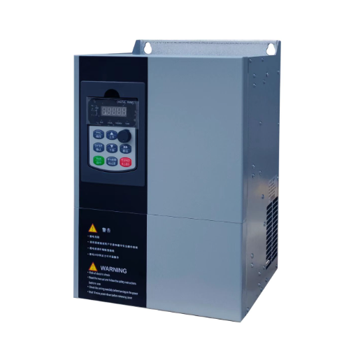
Ready to Get Your VFD Solution?
Whether you need a single drive or a complete system, we have the VFD products and engineering support to ensure your project's success.

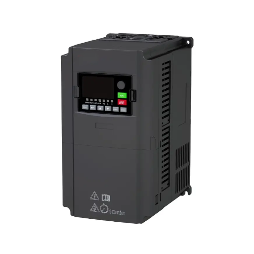
A VFD for extruder duty must be sized to motor FLA on a heavy-duty rating, with vector control and breakaway torque. Follow the steps before you order a drive.
Most extruder drives are not destroyed by running. They are destroyed by starting.
A VFD for extruder duty must be a constant-torque, heavy-duty drive sized to the motor’s full-load current, with vector control and enough short-time torque to break a loaded screw away from rest. Motor kW alone doesn’t tell you whether the drive will start the line. This guide covers industrial plastics and rubber extruders, not the stepper-driven extruder on a 3D printer.
If you have copied a frame size from a pump or fan, the load profile is where the mistake shows. You will get a sizing sequence, a control-mode decision, the motor and gearbox checks, and a first-run checklist.
Send the motor nameplate and screw speed range to our engineers before you order.
Key Takeaways
– Extruders are constant-torque loads. Size the drive to motor FLA at its heavy-duty rating, not to motor kW.
– Breakaway torque with a full barrel can reach 200 to 250 percent of running torque, so a 150 percent for 60 seconds rating may not be enough.
– Sensorless vector is the practical minimum for screw speed stability. Closed-loop vector with an encoder is for tight gauge, low speed, or torque control.
– Measured DC-to-AC retrofit savings range from about 5 to 15 percent. An existing AC drive at full speed may save much less.
– Commission with a loaded barrel, set the torque limit and skip bands, and record a baseline current trace.
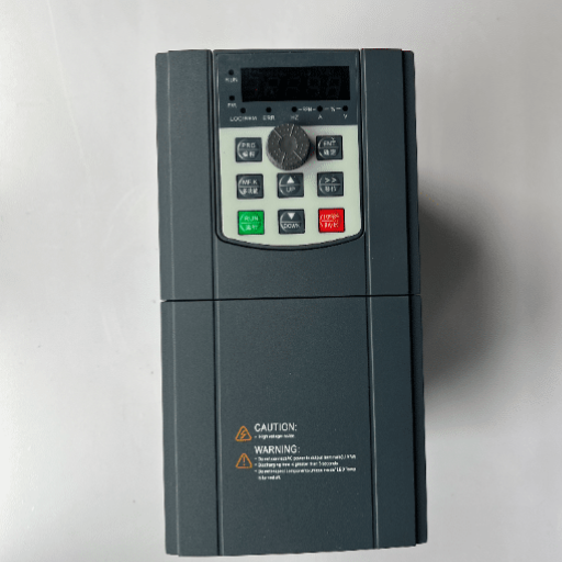
An extruder screw needs roughly the same torque at 30 percent speed as at 100 percent speed. The plastic is viscous, the barrel is hot, and the screw must convey and pressurize the melt regardless of how fast it turns. Power rises with speed because power is torque times speed.
A fan or centrifugal pump is different: torque rises with the square of speed and power with the cube. That’s why normal-duty ratings exist for fans and pumps.
The start is harsher than the run. With a full barrel and cold resin, static friction and viscosity can push breakaway torque to 200 to 250 percent of nominal, according to Danfoss’s extruder application guide. Shandong Electric’s extruder VFD application guide publishes 150 to 200 percent of rated torque at below 1 Hz. Both say the same thing: the drive must deliver current at low frequency, not just at base speed.
This is where normal-duty sizing fails. A drive rated 110 percent for 60 seconds may run the line all day and trip every cold start. The fix isn’t always a bigger kW frame. It may be a heavy-duty rating, a higher current frame, a preheat sequence, or a gear ratio change.
Single-screw and twin-screw extruders are not the same sizing problem. A single-screw line usually has a motor, a gearbox, and one screw. A twin-screw compounder adds a torque-splitting gearbox, two shafts, and axial thrust from melt pressure.
Yaskawa notes that some extruders can run at normal duty, while others need heavy duty. The load profile decides, so don’t copy a single-screw selection onto a twin-screw line.
Daniel runs a 90 kW single-screw pipe line. When the old DC drive failed, the replacement was chosen by motor kW and installed with a normal-duty rating. The line ran all day.
The next Monday, with a full barrel and cold resin, the drive tripped on overcurrent before the screw turned. A heavy-duty drive one frame up, plus a preheat and start sequence, fixed it. The start, not the run, sizes an extruder drive.
Step 1: Record the motor data. Note full-load amps at the site voltage, service factor, insulation class, rated speed, and whether the motor is inverter duty. FLA is the number the drive must supply continuously. kW is a cross-check, not the sizing basis.
Step 2: Choose the duty rating. Use the drive’s heavy-duty or constant-torque current rating and require it to meet or exceed motor FLA. If only a normal-duty current is published, derate or choose a larger frame. Do not assume a 1.15 service factor gives continuous overload. What a 150% overload rating really means is a separate calculation from the breakaway check.
Step 3: Check breakaway torque. Compare the torque needed to start a loaded screw with the drive’s short-time current at low frequency. Danfoss gives 200 to 250 percent of nominal as a worst case; Shandong Electric’s application page gives 150 to 200 percent at below 1 Hz. If the drive cannot cover the peak, you have three options:
Step 4: Derate for the plant. A drive rated at 40 °C may need derating in a hot cabinet. Altitude above 1000 m reduces cooling. Dust calls for a filtered enclosure; the application page lists IP20 and IP54.
| Sizing input | What to record | Why it matters |
|---|---|---|
| Motor FLA | Nameplate amps at site voltage | Continuous drive current |
| Service factor | 1.0 or 1.15 | Continuous overload margin |
| Breakaway torque | Percent of running torque | Short-time current at low frequency |
| Speed range | Minimum and maximum screw rpm | Cooling, field weakening, encoder need |
| Ambient | Cabinet and barrel-side temperature | Drive derating |
| Altitude | Site elevation | Cooling derating |
| Enclosure | IP20 or IP54 | Dust and washdown |
| Control interface | 4 to 20 mA, Modbus, EtherNet/IP, Profinet | PLC integration |
| Cable length | Motor cable run | Reactor or dV/dt filter |
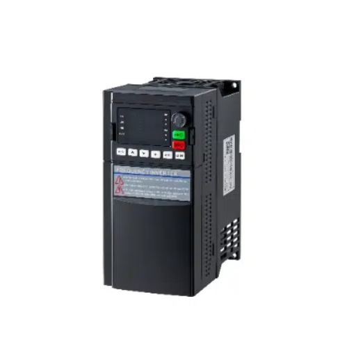
V/F control is not enough for most extruders. It holds a voltage-to-frequency ratio but has no torque or speed feedback. As melt pressure changes, the screw slows and the gauge moves. Use it only for a non-critical line or as a fallback.
Sensorless vector control is the practical minimum. The drive estimates rotor speed and flux from the motor model, so it can hold torque at low speed and correct for load changes. Danfoss publishes better than 0.5 percent speed accuracy in open loop; Shandong Electric publishes 0.5 percent or better for SVC.
Closed-loop vector control adds an encoder. Danfoss publishes better than 0.1 percent speed accuracy, with a maximum deviation of ±1.5 rpm below 1500 rpm. Use it when gauge tolerance is tight, when the line runs at very low speed, or when the PLC closes a torque loop.
Torque limit matters as much as the mode. Set it to the mechanical rating of the screw and gearbox, not the motor’s maximum. On a cold start, the limit protects the screw from a jam and the gearbox from a shock. If a PLC closes the outer speed or pressure loop, run the drive in torque control so the two loops do not fight.
| Mode | Published speed accuracy | Encoder | Best use | Limitation |
|---|---|---|---|---|
| V/F | Not typically published | No | Simple, non-critical lines | Speed droops with load; low torque at low speed |
| Sensorless vector | Better than 0.5% (Danfoss); 0.5% or better (Shandong Electric) | No | Most single-screw lines | Needs correct motor model and auto-tune |
| Closed-loop vector | Better than 0.1% (Danfoss) | Yes | Tight gauge, low speed, torque control | Encoder, wiring, and coupling add cost |
Maria is a process engineer on a blown-film line. The drive held average speed well, but gauge bands moved across the roll whenever melt pressure changed. The speed reference came from a noisy 4 to 20 mA signal.
An encoder, closed-loop vector, a shielded reference cable, and a speed-loop tune reduced the variation. Stability depends on what you measure and how you feed the loop.
If you are still weighing modes, compare VFD control modes before you compare brands.
The drive is only one part of the train.
Use an inverter-duty extruder motor for a line that runs below base speed for long periods. PWM output puts voltage stress on the winding, and a shaft-mounted fan cools less as speed falls.
NEMA MG-1 calls for derating a standard motor below about 25 percent of base speed without separate cooling. A separately powered blower, or a larger inverter-duty motor, avoids the problem. How to cool a motor at low speed covers the thermal side in more detail.
Check the extruder gearbox before the drive. Its continuous torque rating, thermal rating, and service factor may set the limit before the motor does. On a twin-screw compounder, the torque splits between two shafts, and axial thrust from melt pressure can exceed 500 kN in large machines and reach 3,400 kN or more. Size from the screws backward, not from the motor forward.
Shaft currents are a real failure mode on larger frames. PWM common-mode voltage can circulate through the bearings. Insulated bearings and a grounding brush are common defenses; ABB lists both for its extruder-duty motors.
Cable length and grounding decide how the control loop behaves. Keep motor cables short, use shielded cable, and separate power from encoder and analog wiring. Over 50 ft (15 m), add an output reactor or dV/dt filter.
The video explains torque control and reflected inertia. It is background, not an extruder start procedure.
Energy savings are real, but they are not a fixed percentage.
The largest savings come from replacing a DC motor and drive. A DC motor has brushes, a commutator, and a separate field supply. An AC motor with a VFD avoids most of that maintenance and usually runs at a better power factor. Danfoss says an AC system with its drive is typically 5 percent more efficient than a comparable DC system.
Davis-Standard’s lab trial on a 2.5-inch (64 mm) 30:1 extruder found the DC system consumed 5 to 15 percent more power than the AC system in the operating range. ABB’s Radius Systems retrofit, a 182 kW DC motor replaced with a 200 kW IE4 SynRM motor and ACS880, reported 8 to 15 percent lower energy use and up to 15 percent lower kWh/kg.
Process improvements can matter more than energy. Tighter screw speed holds gauge, reduces scrap, and cuts changeover time. Shandong Electric’s application page cites up to 30 percent versus older DC or hydraulic systems, and a customer testimonial cites 25 percent. Treat those as company claims; the measured third-party ranges above are 5 to 15 percent.
When the savings are small: an existing AC drive running at full speed most of the time. A VFD may still pay for soft starting and quality, but the energy case is weak. Measure before and after with a power logger, then calculate kWh saved as (power before minus power after) times hours times load factor.
Before you order, record the motor nameplate, FLA, insulation condition, cable length, ambient temperature, and start condition. Megger the existing motor before you connect a new drive. A motor that fails an insulation test will fail again.
Set these parameters before the first production run:
The first loaded start is the real test. Preheat the barrel, confirm rotation, start at low speed, and watch motor current. If the drive trips, check the breakaway assumption, the motor data, the torque limit, and the mechanical path before you change the drive.
Speed pulsation is usually a system problem. The motor and load are two masses connected by a compliant gearbox, coupling, or belt. A skip band, a softer ramp, a stiffer coupling, or a detuned speed loop can remove the resonance.
Check the encoder coupling and the ground before you blame the control loop. Industrial Monitor Direct’s field guide lists the same order: baseline, motor, cabling, drive, then process.
| Symptom | Likely cause | First check |
|---|---|---|
| Trip on loaded start | Breakaway torque above drive short-time rating | Motor FLA, duty rating, start temperature |
| Speed pulsation at one speed | Resonance between motor, gearbox, and screw | Skip band, coupling, speed-loop gain |
| Overcurrent on acceleration | Ramp too short or torque limit too high | Ramp time, torque limit, mechanical drag |
| Motor hot at low speed | Shaft fan too slow; no separate cooling | Blower, motor derating, minimum speed |
Ahmed commissioned a 25 HP extruder drive at a compounding plant. The line ran well at 30 Hz and at 50 Hz but pulsed violently around 38 Hz. The drive was not faulty.
The pulse was a resonance between the motor, gearbox, and screw. A skip band from 36 to 40 Hz, a softer ramp, and a slightly detuned speed loop removed it. The line lost a small part of its speed range and gained a stable process.
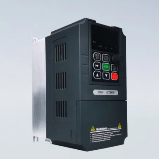
When you choose a VFD for extruder duty, match the series to the line, then verify the current rating at your motor voltage.
| Series | Published control | Published overload | Best fit |
|---|---|---|---|
| YC-1610 | V/F and SVC | Not published on the application page | Small single-screw, lab, and downstream drives, 0.75 to 55 kW, 220 to 480 V |
| YC-1800 | V/F and open-loop vector | 150% for 60 s | Small general-purpose lines, 0.01 Hz resolution, asynchronous and synchronous motors |
| YC-5000 | V/F, SVC, and FVC | 150% for 60 s; 180% for 10 s | Heavy-duty single-screw and twin-screw lines that need low-speed torque or encoder feedback |
The YC-5000 heavy-duty vector VFD product page publishes 200 percent torque at 0.5 Hz, 150 percent for 60 seconds, 180 percent for 10 seconds, and ±0.01 percent speed regulation with the optional PG card. It does not publish a speed-loop bandwidth or a guaranteed energy saving. If your line needs a response number, ask for a test on your motor and load.
The application page lists a constant-torque rating at or above motor FLA, 150 to 200 percent starting torque at below 1 Hz, 150 percent for 60 seconds, and 0.5 percent or better speed regulation in SVC. Use that as the minimum, then add the breakaway check.
What size VFD do I need for an extruder?
Size a VFD for extruder duty by the motor’s full-load amps at the heavy-duty rating, not by motor kW. Then check that the drive can deliver the breakaway torque needed to start a loaded screw. If it cannot, go one current frame up or change the start sequence.
Can I use a normal-duty VFD on an extruder?
Usually no. A normal-duty rating is designed for variable-torque fans and pumps, and it may trip on a loaded start. Yaskawa notes that some extruders can run at normal duty, so verify the torque profile and start condition before you accept the lower rating.
Do I need an encoder on an extruder VFD?
Not always. Sensorless vector holds screw speed within about 0.5 percent on many lines. Use an encoder when gauge tolerance is tight, when the line runs at very low speed for long periods, or when the PLC closes a torque loop.
Will a VFD save energy on my extruder?
It depends on what you are replacing. A DC-to-AC retrofit typically saves 5 to 15 percent in published cases. An existing AC drive running at full speed may save much less. Measure the before and after power, not the brochure claim.
Why does my extruder VFD trip at startup?
The most common causes are breakaway torque above the drive’s short-time rating, incorrect motor data, a normal-duty drive on a constant-torque load, and a torque limit set too low. Check those before you replace the drive.
Can a VFD run a twin-screw extruder?
Yes, but size it from the gearbox shaft torque, specific torque, and axial thrust, not motor kW alone. Twin-screw gearboxes often have a service factor of 1.75 to 2.25 for high-filler compounds, and cold starts can add 20 to 40 percent torque.
A VFD for extruder duty comes down to four decisions: the duty rating, the motor FLA, the breakaway torque, and the control mode. Get those right, and the drive will start a loaded screw, hold speed as melt pressure moves, and protect the gearbox from a cold-start shock. Get them wrong, and a larger drive will not save you.
Before the first production run, preheat the barrel, set the torque limit, add a skip band if the line resonates, and record a baseline current trace. That trace is the reference for every fault that follows.
Send the motor nameplate, the screw speed range, and the start condition to our engineers. We will check the current rating for your VFD for extruder duty against the load, not just the kW.