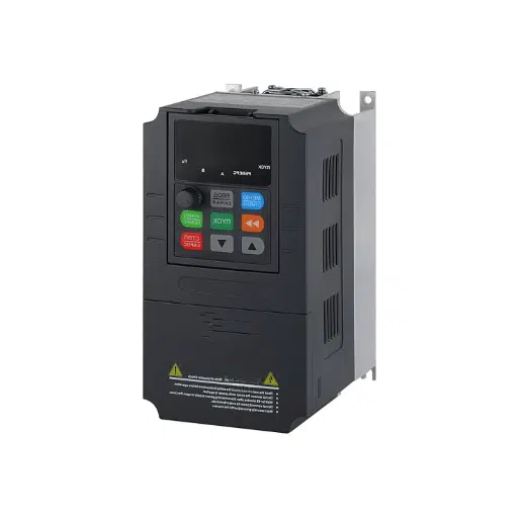
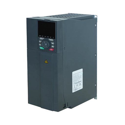
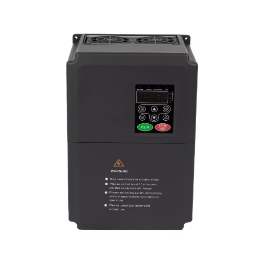
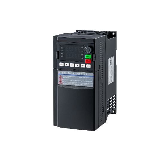
Ready to Get Your VFD Solution?
Whether you need a single drive or a complete system, we have the VFD products and engineering support to ensure your project's success.

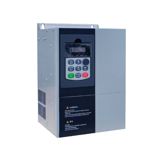
VFD tension control holds web tension with torque, not speed. Compare open-loop, load-cell, and dancer control, then size the motor and commission the drive.
VFD tension control regulates motor torque, not speed. Torque equals tension times roll radius, so the drive must know the radius and change torque as the roll builds or depletes.
This guide to web tension control covers film, foil, paper, textile, wire, and cable. It does not cover tension control bolts or sewing machine thread tension. Send the motor nameplate, roll data, and line speed to our engineers before you order.
Key Takeaways
- A VFD holds tension with torque, not speed. Torque equals tension times radius, so torque must rise as a rewind grows.
- Open-loop diameter tracking suits roughly a 10:1 diameter ratio. A load-cell loop reaches about 15:1, and a dancer adds web storage and damping.
- A standard VFD is not a center-winder controller unless something calculates diameter. Confirm whether diameter, taper, and inertia live in the drive or the PLC.
- Size for full-roll torque and core-diameter speed, then add acceleration torque. Roll inertia rises with the fourth power of diameter.
- Commission torque limit, speed override, friction, inertia, taper, and web-break detection before the first production roll.
A tension zone is the span between two driven or braked rolls. A typical line has unwind, intermediate, and rewind zones, each with its own reference and feedback.
Tension = torque / radius, or torque = tension × radius.
A 200 N pull at a 0.5 m radius needs 100 Nm at the roll shaft. The same 200 N at a 0.1 m core needs only 20 Nm. If the drive applies fixed torque, tension falls as a rewind builds and rises as an unwind depletes.
At the motor, divide by the gear ratio and efficiency:
Motor torque = tension × roll radius / (gear ratio × efficiency).
With 200 N, a 0.5 m radius, a 2:1 gearbox, and 0.95 efficiency, the motor needs 52.6 Nm. At the core, it needs 10.5 Nm.
At constant tension and speed, power = tension × web speed. A 200 N pull at 4 m/s needs 800 W at any diameter. The motor trades torque for speed as radius changes, so check both ends of the roll.
A speed-controlled drive holds shaft speed. If the web stretches, the loop keeps turning at the same rate and tension changes.
ABB’s application note gives an example. A web with EA = 200 N accelerated from 100 to 102 m/min sees a 4 N tension rise. A 0.25% error in that speed change produces 4.51 N, a 12.75% tension error. A 0.25% torque error produces a 0.25% tension error. Use torque control unless the web is very stretchy.
Sensorless vector control is the practical minimum for torque control. Closed-loop vector with an encoder is for low speed, tight tension, or a standstill hold. If you are comparing modes, compare VFD control modes first.
Priya runs a packaging converter with an unwind dancer. The dancer signal was wired to speed trim, but the drive stayed in speed control with a low torque limit. The dancer sat at its stop and tension wandered. Torque mode, a higher torque limit, and a tuned dancer loop fixed it.
Holding tension at standstill is thermal: the drive can command torque at zero speed, but the motor must tolerate it. Torque at zero speed covers the motor side.
A tension control system can use any of these three. Printing presses and packaging lines use the same three; the printing press VFD guide covers register and line-shaft synchronization.
| Architecture | What the drive needs | Web feedback | Typical fit | Main limit |
|---|---|---|---|---|
| Open-loop torque with diameter tracking | Tension reference, diameter, gear ratio | None | Center winders, draw zones, simple surface winders | Friction, inertia, and diameter errors go uncorrected |
| Load-cell closed loop | Load cell, tension reference, diameter | Actual tension | Film, foil, paper, critical tension | Load cell cost, wrap angle, web contact, overload risk |
| Dancer position control | Dancer, position sensor, line speed | Dancer position | Out-of-round rolls, splices, roll changes, elastic webs | Space, mechanical design, slower response |
This is classic indirect tension control. The drive calculates torque from the tension reference, gear ratio, and diameter, without web feedback. ABB’s guide calls diameter calculation the most important part.
Open loop is simple and inexpensive. It cannot see friction, inertia, or a diameter error, so friction compensation is essential. ABB recommends measuring static and speed-dependent friction separately.
Siemens’ guide lists the indirect-control envelope: about a 10:1 diameter ratio, a 6:1 tension range, a combined 40:1, and up to 600 m/min.
A load cell measures actual web tension. In torque trim, the speed controller is overdriven to its torque limit and the tension PID trims the torque reference. In speed trim, the PID corrects the speed reference. ABB’s ACS880 guide supports both. Torque trim is common on center winders; speed trim suits elastic webs.
The load cell needs the correct wrap angle, stable mounting, and a signal filtered to reject vibration without hiding a tension swing. Siemens lists about a 15:1 diameter ratio, a 20:1 tension range, a 100:1 combined range, and up to 2,000 m/min for load cell tension control.
A dancer is a preloaded idler arm. Web tension pushes against a support force, and the arm moves when tension changes. The drive provides dancer tension control by regulating position, usually through speed trim. It is a position controller, not a direct tension sensor.
Its advantage is storage: the dancer holds web length that absorbs an out-of-round roll, a splice, or a roll change. Siemens lists about a 15:1 diameter ratio, a combined range up to 40:1, and speeds above 2,000 m/min. Its cost is space, and a poorly sized dancer or drifting support force causes more problems than it solves.
On a surface winder, the roll is driven by contact with a roller or nip. The nip and dancer set tension, and the winder drive mainly follows speed. Danfoss’s VLT 5000 winder option (a reproduced manual) is for constant-tension surface winders and is not suitable for center winders because it has no radius compensation.
On a center winder, the roll is driven from its core. Torque must rise with radius, so the drive or PLC must calculate diameter. A standard drive in torque mode with a fixed reference will produce rising tension as the roll builds.
Tomas found this on a wire-and-cable rewinder. A standard VFD ran in torque mode with a reference set for the core. As diameter grew, tension climbed until the wire began to neck and the drive hit its torque limit. Diameter tracking, a taper, and a load cell trim for the outer layers fixed it. The drive could control torque. It could not know the radius.
Shandong Electric’s YC-5000 publishes V/F, sensorless vector, closed-loop vector, and torque control, with 200% startup torque at 0.5 Hz and 150% overload for 60 s. It does not publish a built-in winder function, so a center winder needs a PLC or dedicated controller to own diameter and taper. The YC-5000 low-voltage VFD is the drive to review when the motor needs closed-loop vector and an encoder.
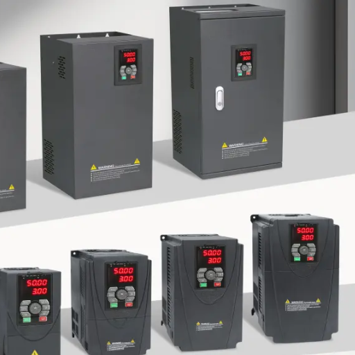
In open loop, a 1% diameter error is a 1% torque and tension error. Diameter tracking is not a detail.
With a reliable line-speed signal and a motor or roll encoder:
D = line speed / (π × roll speed).
With a gearbox, roll speed is motor speed divided by the gear ratio. Keep units consistent. For 300 m/min (5 m/s) and a roll turning at 100 rpm (1.667 rev/s), D = 5 / (π × 1.667) = 0.955 m.
This method needs a minimum speed: at very low speed, encoder resolution and noise dominate. A drive with a winder function holds diameter at stop and needs a reset when a new core is loaded.
The cross-section of wound material is an annulus:
Length × thickness = π/4 × (D² − D_core²).
Rearranged:
D = √(D_core² + 4 × length × thickness / π).
For a 150 mm core, 10,000 m of 50 µm film, and no air entrainment, D = √(0.15² + 4 × 10,000 × 0.00005 / π) = 0.81 m. The result is sensitive to thickness, air inclusion, and web tension. Reset at every core change.
A direct sensor avoids those assumptions. An ultrasonic or laser sensor measures the roll surface; a follower arm tracks it mechanically. ABB’s guide allows an external feedback device, or one used at stop to correct an estimate.
Direct measurement is most reliable for a large roll build or surface winder, where the speed ratio is hard to trust. It adds a sensor and calibration, plus a filter so a splice does not step the torque reference.
Whichever method you use, set core diameter, full diameter, initial diameter, filter, and reset logic. A wrong initial diameter produces a tension bump at every roll change.
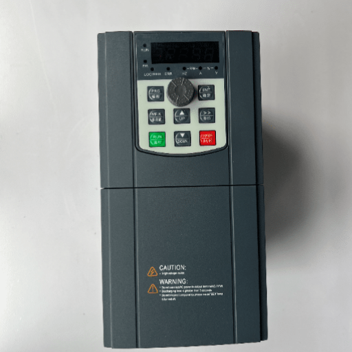
Sizing for VFD tension control starts at the roll, not the motor nameplate. Work through torque and speed at both ends, then add acceleration and regeneration.
Step 1: Define the tension range and web width. Convert newtons, newtons per meter, or pounds per linear inch to total tension. The maximum sets torque; the minimum sets turn-down. As a guide, ABB suggests keeping maximum tension below 25% of the elastic limit.
Step 2: Calculate full-roll torque. A 200 N tension at a 0.5 m radius needs 100 Nm at the roll. Divide by gear ratio and efficiency: with 2:1 and 0.95, the motor needs 52.6 Nm.
Step 3: Calculate core-diameter speed. The motor runs fastest when the roll is empty. With a 0.2 m core and 4 m/s line speed, roll speed is 4 / (π × 0.1) = 12.7 rev/s, or 764 rpm. A 2:1 gearbox gives 1,528 rpm. Check it against motor and drive limits.
Step 4: Add acceleration torque. Roll inertia:
J = 0.5 × π × density × width × (R_out⁴ − R_in⁴).
The fourth power matters: a full 800 mm roll on a 150 mm core carries about 54 times the material inertia of a 300 mm roll on the same core. Acceleration torque is J times angular acceleration and can exceed running torque on a fast ramp. Size on RMS torque over the cycle.
Step 5: Check unwind regeneration. An unwind motor is driven by the web and generates. A brake chopper and resistor dissipate the energy; a shared DC bus sends it to another drive; a regenerative front end returns it to the supply. Danfoss specifies a chopper or DC-link sharing.
| Sizing input | What to record | Why it matters |
|---|---|---|
| Tension range | Minimum and maximum total tension | Torque and turn-down ratio |
| Roll geometry | Core diameter, full diameter, width | Torque, inertia, speed range |
| Material | Density, thickness, elastic limit | Inertia, diameter tracking, safe tension |
| Line speed | Minimum, maximum, ramp times | Core-diameter motor speed, acceleration torque |
| Gearbox | Ratio, efficiency, torque rating | Motor torque and speed |
| Motor | FLA, rated torque, max speed, insulation | Drive current and thermal margin |
| Duty cycle | Roll changes per hour, acceleration frequency | RMS torque and brake resistor duty |
| Unwind or rewind | Direction of power flow | Brake chopper, shared bus, or regenerative front end |
| Feedback | Encoder, load cell, dancer, line-speed signal | Architecture and control mode |
Aisha runs a film line with a center rewinder. The motor was sized for running tension and ran all day at steady state. On a fast acceleration with a full roll, the drive tripped on overcurrent. Acceleration torque was the problem. A new RMS calculation, a longer ramp, and one frame up fixed it.
Commission VFD tension control in this order. A skipped step usually looks like a tuning problem.
Without a winder function, the PLC must handle diameter, taper, friction, and inertia. The drive still needs scaling, limits, and web-break logic.
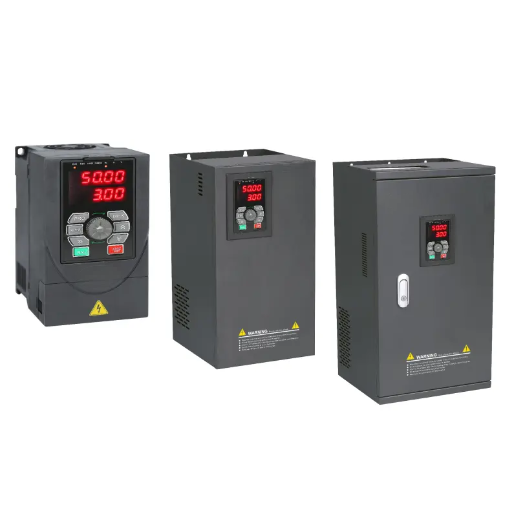
A VFD suits a large roll, moderate speed, and a tension tolerance that diameter-based control can meet.
Use a servo when the tension loop must be fast, the roll must reverse, or the drive must hold position as well as torque. A servo costs more but gives torque response and low-speed control a general-purpose VFD cannot match.
Use a dedicated tension controller when you want a proven load-cell or dancer loop and a drive in torque or speed follower mode.
Use a magnetic particle brake or clutch on a simple unwind where constant torque is acceptable and the diameter range is small. Tension rises as the roll depletes, so it suits a small build ratio.
Use a mechanical solution when a surface winder, differential shaft, or dancer already sets tension and the drive only follows speed. A torque loop can make it worse.
If the job needs more than about 10:1 in open loop, or 15:1 with a load cell, change the mechanics or architecture before the drive.
How does VFD tension control work?
The drive regulates motor torque so the web sees the required pull. Torque equals tension times radius, so the drive needs a diameter reference and a torque reference. Open loop calculates torque from diameter; closed loop corrects it with a load cell or dancer.
Can a VFD control web tension without a load cell?
Yes. Open loop uses a calculated or measured diameter and no web feedback. It cannot correct friction, inertia, or a diameter error.
Does a VFD need an encoder for tension control?
Not always. Sensorless vector can run a torque loop at moderate speed. An encoder and closed-loop vector are better for low speed, standstill holding, and tight tension. The YC-5000 publishes ±0.01% speed regulation with its PG card, but speed accuracy is not tension accuracy.
What is the difference between dancer and load-cell tension control?
A dancer controls a preloaded arm’s position and provides web storage, absorbing splices and out-of-round rolls. A load cell measures tension directly and responds faster, but has no storage.
Can a VFD run an unwinder?
Yes, but the motor generates. You need a brake chopper and resistor, a shared DC bus, or a regenerative front end. Do not apply taper tension to an unwinder; taper is for building a roll.
Why does tension change as the roll builds?
Winder tension control depends on radius, so fixed torque produces changing tension. Other causes are diameter error, missing taper, friction that changes with speed, and inertia during acceleration. Check diameter, then friction and inertia, then tuning.
VFD tension control is a torque problem with a diameter input. Get the architecture right and most drives can execute it. Get it wrong and a larger drive will not help.
Start with the roll: core and full diameter, width, material, tension range, and line speed. Decide where diameter lives, then size for full-roll torque, core speed, acceleration, and regeneration.
If you are retrofitting a winder, send the line data to our engineers. We can review the architecture, drive rating, and motor match.