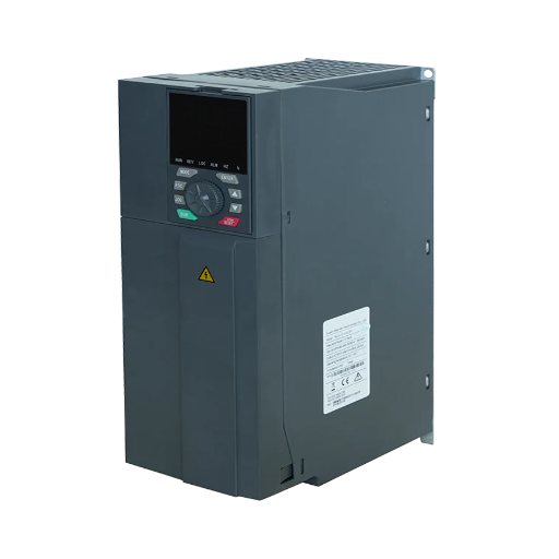
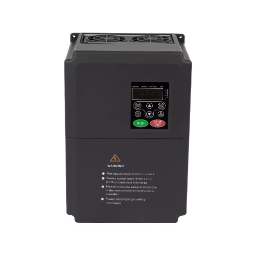
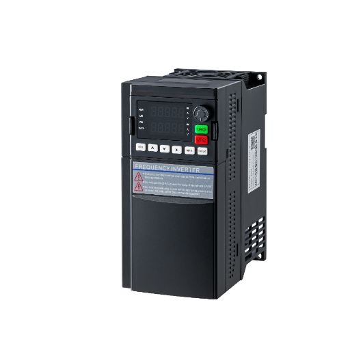
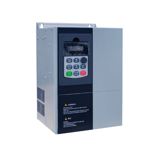
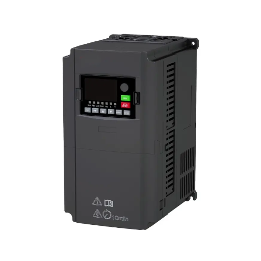
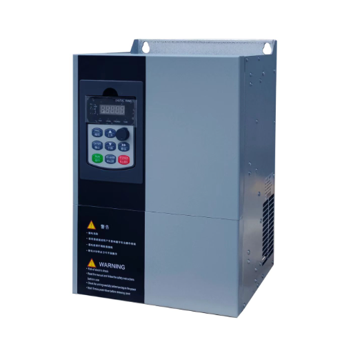
Ready to Get Your VFD Solution?
Whether you need a single drive or a complete system, we have the VFD products and engineering support to ensure your project's success.

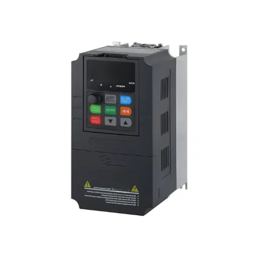
Low voltage VFD systems must match the plant supply, not just the motor. Check voltage class, earthing, tolerance, and multi-motor limits before you buy.
A low-voltage VFD system is specified by the supply first: the voltage class, earthing arrangement, tolerance, frequency, and phase balance decide whether a standard drive can be installed at all. The motor nameplate sets the current rating, but the supply sets the drive family.
Consider Elena, a plant engineer who orders a 690 V drive for a new 690 V motor. The drive arrives, the electrician reads the supply label, and the project stops. The supply is a corner-grounded delta, and the drive manual says it must not be installed there.
You have probably compared drives by kW, HP, and control mode. Those numbers matter, but they don’t cover the supply interface, which rejects more projects than the motor rating does. This guide gives you five supply values to record, the earthing systems that need approval, and when 690 V pays. If you have a supply schedule, send it to our engineers with the nameplate.
Key Takeaways
- A “400 V” drive is a range, not a point. One ABB 400 V class accepts 380 to 415 V at +10%/-15%.
- A standard drive assumes a symmetrically grounded TN-S supply. IT, TT, and corner-grounded delta systems need specific approval or hardware changes.
- ABB states that its 690 V drives must not be installed on 525 to 690 V corner-grounded or midpoint-grounded delta systems.
- The same power at 690 V draws about 42% less current than at 400 V, but the saving only pays above roughly 5.5 kW and with a suitable transformer winding.
- One drive can run several motors only in V/f mode, at a rated current of at least the sum of motor currents times 1.1, with a separate overload relay per motor.
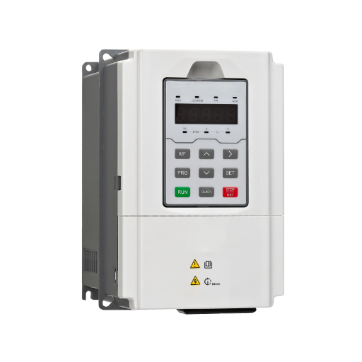
IEC 60038 covers AC systems from 100 V to 1,000 V and lists 230/400 V and 400/690 V as standard three-phase values (IEC 60038). Drive makers split that band into narrower classes because semiconductors, clearances, and cooling change with voltage.
The common drive classes are:
The classes overlap because a drive accepts a band. The same 400 V class may be sold as 380 to 415 V or 380 to 500 V, and a 690 V class typically starts at 525 V.
The class isn’t the motor voltage. A low-voltage variable frequency drive can feed a motor at any frequency and voltage up to its input rating, if the V/f ratio and insulation allow it. The class fixes the input side: components, clearances, and price.
A 480 V supply and a 400 V quote is the common mismatch. The 400 V class may stop at 415 V, while the 480 V class starts around 440 V. The quote bracket, not the kW rating, decides.
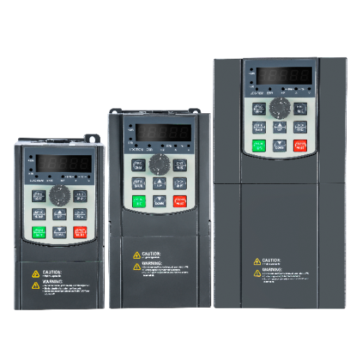
Five values screen most projects before a quote. Record them from the transformer nameplate, the protection study, or a power quality logger.
| Value | What to record | Published example | Why it matters |
|---|---|---|---|
| Voltage class | Nominal line-to-line voltage and phase count | ABB ACS880-01 400 V class: 380 to 415 V, +10% to -15% | Outside the band, the drive trips or won’t start |
| Earthing system | TN-S, TN-C, TT, IT, or delta arrangement | ABB standard drive: symmetrically grounded TN-S | Some systems need filter changes or rule out the drive |
| Frequency | 50 Hz or 60 Hz, plus expected variation | ABB: 50/60 Hz, ±5%, maximum rate of change 17%/s | Frequency error changes motor speed and V/f ratio |
| Phase imbalance | Maximum voltage difference between phases | ABB: 3% of nominal phase-to-phase voltage | Imbalance heats the rectifier and creates DC bus ripple |
| Fault level | Available short-circuit current at the drive terminals | From the protection study | Sets the drive and panel short-circuit rating |
ABB publishes +10% to -15% for its ACS880-01 input ranges, including 380 to 415 V and 525 to 690 V (ABB ACS880-01 manual). Nidec publishes 380 to 480 V at ±10% and 500 to 690 V at ±10% for the Unidrive M. Neither figure is universal. Read the input table for the exact model, not the marketing class.
The negative tolerance causes nuisance trips. A 400 V drive with -15% accepts 340 V. A weak transformer and a large motor start can dip below that, tripping the drive on undervoltage while nominal voltage looks correct.
ABB specifies 50/60 Hz with ±5% variation and a maximum rate of change of 17% per second. That covers normal grid variation, not a generator set with poor regulation.
The V/f ratio explains why. A 400 V, 50 Hz motor and a 480 V, 60 Hz motor both have a ratio of 8, so each can run on either supply if insulation and cooling allow. A 400 V, 50 Hz motor on a 480 V, 50 Hz supply has a ratio of 9.6, which pushes flux and current up.
ABB limits input imbalance to 3% of nominal phase-to-phase voltage. Above that, the rectifier diodes carry unequal currents, the DC bus ripple rises, and capacitors run hotter.
Karim’s plant in the Middle East logged 2.9% imbalance for months. During a weekend load change it crossed 4%, and three drives on the same bus tripped on undervoltage within an hour. The drives were blamed; the supply was the cause.
If the imbalance is above the drive limit, fix the supply or add a line reactor. Don’t solve it by raising the trip delay.
For the component-level selection method, see the complete guide to low voltage VFD selection.
The case for 690 V is current. For the same power, current falls with voltage. Because 690 V is √3 times 400 V, current is about 42% lower. At 250 kW, with a power factor of 0.95 and efficiency of 0.96, a 400 V motor draws about 396 A. At 690 V it draws about 229 A.
Schneider Electric states that 690 V allows motors up to 335 to 350 kW to run on low voltage, where 400 V practice stopped at 200 to 250 kW. It also states that switching from 400 V to 690 V doesn’t significantly change cost, but it reduces cable cross-section or cable losses (Schneider Electric).
The savings have conditions:
Above roughly 800 kW to 1 MW, medium voltage usually wins, because cable and switchgear costs erase the 690 V advantage. See the low voltage vs high voltage drive comparison.
Sofia’s food plant in northern Europe consolidated six 400 V motors onto a 690 V bus during an expansion. The 250 kW line motor dropped from a 3 by 185 mm² cable to a 3 by 95 mm² cable, and the panel width fell by one section. The plant had to add a 690 V winding to the new transformer, which was already being replaced. Without that replacement, the project wouldn’t have paid.
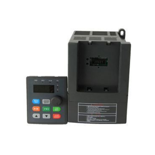
The supply voltage tells you which drive class to quote. The VFD earthing system tells you whether that drive can be connected at all.
In a TN-S system, the neutral and protective earth are separate conductors from the transformer to the load. It’s the default assumption for a standard drive.
In a TN-C system, the neutral and protective earth are combined in one PEN conductor. A drive needs a separate protective earth, so the PEN must be split before the drive. That’s a design change.
In a TT system, the transformer neutral is earthed at the source and the installation has its own local earth electrode. Earth fault current returns through the ground, so protection depends on an RCD or earth fault relay. A drive with a large built-in EMC filter can leak enough current to trip a sensitive RCD.
In an IT system, the supply is unearthed or earthed through a high impedance. A single earth fault doesn’t trip the supply, which is why hospitals and marine systems use it. A drive on IT needs its EMC filter and varistor evaluated and often disconnected.
ABB states that its standard drive can be installed on a symmetrically grounded TN-S system. For any other system, the EMC filter and ground-to-phase varistor may need to be disconnected. That reduces EMC performance, so it’s a documented modification, not a field guess (ABB ACS880-01 manual).
A corner-grounded delta has one phase connected to earth. A midpoint-grounded delta has the midpoint of one winding earthed. Both appear in older North American plants and some marine systems.
The rule is drive-specific. ABB states that its 690 V drives must not be installed on 525 to 690 V corner-grounded or midpoint-grounded delta systems, and that disconnecting the EMC filter and varistor does not prevent damage. Lower-voltage frames may allow it with documented modifications, but the frame manual decides.
This is where low-voltage VFD systems fail after the order. The motor and drive are correct, but the supply isn’t rated for the drive, and no kW comparison catches it.
The video below explains why grounding and shielding matter in VFD circuits. It is third-party background, not a procedure for any specific drive.
For the wiring and commissioning steps, see the low voltage VFD installation guide.
A multi-motor VFD setup can run several motors, but only under conditions many buyers miss. Yaskawa’s application note sets the rules:
The overload rule causes failures. A drive’s electronic thermal model assumes one motor. With three motors on the output, it can’t tell which one is overloaded, so one motor can burn while total current stays within the drive rating.
Daniel’s water utility ran three 30 kW aeration blowers from one 110 kW drive to save panel space. The drive was set to sensorless vector, and it tripped on overcurrent every time the third blower started. The fix was to switch to V/f, add a separate overload relay to each blower, and start the blowers through the drive’s sequence. The drive was sized correctly. It was configured for the wrong system.
Use separate drives when motors need independent speed, position control, or fault isolation. A shared drive is a cost and space decision, not a control strategy.
Total cable to all motors counts. Long runs may need an output reactor or dV/dt filter. See VFD motor cable length limits for the method.
For low voltage VFD systems, a supplier can’t confirm compatibility from kW. Send these ten values:
The first six decide the drive family; the last four the rating and options.
At 690 V, the transformer winding and motor insulation become pass or fail items, not preferences. Our low voltage VFD systems page lists the series we supply, and the YC-5000 is the model to start with for 690 V and vector control. Confirm the network type and voltage class in writing before the order.
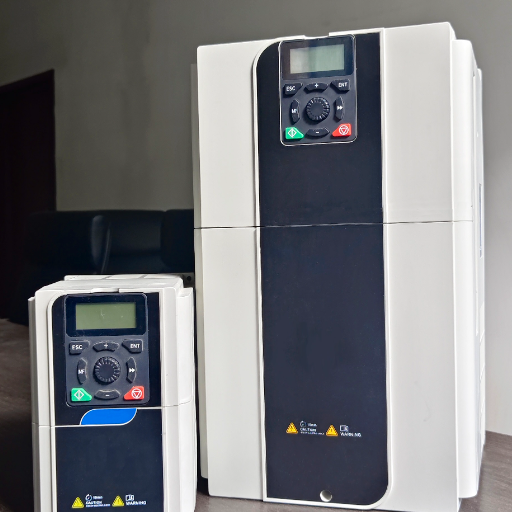
These six checks at commissioning catch what a datasheet review misses.
Log the results with the drive parameters. Later faults trace back to the supply or the drive.
Low voltage for a VFD means the IEC band up to 1,000 V AC, but drives are built in narrower classes: 208 to 240 V, 380 to 480 V, 525 to 600 V, and 525 to 690 V. The datasheet class, not the generic term, decides what the drive accepts.
Usually not. A 400 V class often stops at 415 V. A 480 V VFD or 500 V class is the safer quote, because its input table covers 480 V. Check the range at +10% of nominal.
ABB states that its 690 V drives must not be installed on 525 to 690 V corner-grounded or midpoint-grounded delta systems, and that removing the filter and varistor does not prevent damage. Other makers differ; the drive manual decides.
Yes, in V/f mode, with a drive rated at least the sum of the motor currents times 1.1 and a separate overload relay on each motor. The motors start and stop together, and no motor can use encoder feedback.
No. A three-phase drive connects to the three line conductors and the protective earth. A neutral may be needed for a control transformer or a 220 V control circuit, but that is a separate supply.
The rectifier carries unequal currents, DC bus ripple rises, and capacitors and diodes run hotter. The drive may trip on undervoltage or overvoltage. Fix the supply, add a line reactor, or derate the drive, but don’t raise the trip delay to hide the problem.
Low voltage VFD systems aren’t selected by kW and control mode alone. The supply class, earthing, tolerance, frequency, and imbalance decide whether a standard drive can be installed and how long it will last.
Use the five-value screen before you request a quote: voltage class, earthing, frequency, imbalance, and fault level. Then send the supply data sheet and motor nameplate, and ask for the network rating in writing.
If you’re planning a system now, send your supply details and motor nameplate to our engineers. We’ll check the drive class, the 690 V option, and the earthing arrangement before the order.