Ready to Get Your VFD Solution?
Whether you need a single drive or a complete system, we have the VFD products and engineering support to ensure your project's success.

There’s no single maximum length for a VFD motor cable. The limit depends on two numbers that a specifier usually has to dig out of a manual: the motor’s insulation withstand rating and the drive’s output rise time. Together those set the critical length, and everything else follows from it.
Here is how much the answer moves. On one manufacturer’s published tables, a 230 V motor runs 600 feet of cable at any carrier frequency. A 575 V motor at 12 kHz runs 15 feet. Same drive architecture, same cable, a 40-to-1 difference driven entirely by voltage class and switching speed.
Tariq found that asymmetry the expensive way. A project engineer at a water treatment plant in Oman, he specified a 575 V pump installation in 2024 and reused the cable schedule from a 400 V job on the same site. The run was 30 metres, which had been unremarkable on the lower-voltage system. At 575 V it was well past the limit, and the motor failed on a winding short eleven months into service.
This VFD long motor cable guide gives you the published length limits, the formula behind them, and the two standards that decide what the motor has to survive. It is about how long the run can be, and why.
If you have a cable schedule and want the limits checked against the drive and motor you are using, send us the run length, the voltage class and the motor details and our engineers will work it through.
Key Takeaways
- There is no universal maximum cable length. The limit depends on motor insulation rating, drive rise time, carrier frequency, voltage class and cable type, and published tables vary widely between manufacturers.
- Carrier frequency and voltage class dominate. On published figures, a 230 V motor allows 600 ft at any carrier frequency, while a 575 V motor drops from 40 ft at 3 kHz to 15 ft at 12 kHz.
- The critical length is calculable. L = (v x t_rise) / 2, with propagation velocity around 150 to 160 m per microsecond and modern IGBT rise times of 0.05 to 0.4 microseconds. That puts a typical critical length between roughly 4 and 30 m.
- NEMA MG 1 Part 31 requires motors to withstand 1,600 V at 0.1 microsecond rise time. IEC TS 60034-25 sets 1,560 V for 500 V systems and 2,150 V for 690 V systems. A motor compliant with one is not automatically compliant with the other.
- Long cables fail in two different ways. Reflected-wave overvoltage stresses the motor, and charging current stresses the drive. They have different symptoms and different fixes.
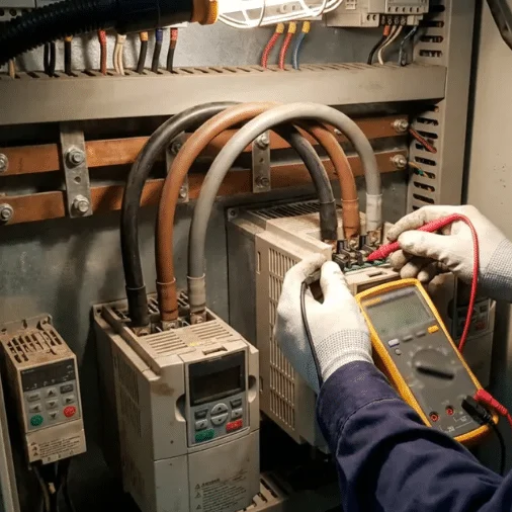
A motor cable isn’t a wire. At the switching speeds modern drives produce, it behaves as a transmission line with distributed capacitance and inductance, and a fast voltage edge travelling down it reflects back from the motor.
If the run is short, the reflection settles before the next edge arrives. If it’s long enough, the reflection arrives just as a new edge is launched and the two superimpose, pushing the peak voltage at the motor terminals toward twice the DC bus voltage. There is a full explanation of the mechanism, and of which output filter addresses it, in our dV/dt filter versus sine wave filter comparison.
That article answers which device to buy. This one answers how long the run can be. They are different questions, and the second one has numbers attached that the first deliberately leaves open.
Long runs cause problems in two distinct places, and confusing them wastes time.
On the motor side, reflected-wave overvoltage erodes winding insulation. It shows up as a motor failure months or years later, and it’s what the insulation ratings in this guide are about.
On the drive side, cable charging current trips the drive. The cable’s capacitance is recharged on every switching event, and that current has to come from the drive’s output stage. It shows up as an overcurrent or ground fault trip, often at low output frequency, and it can appear on a drive whose motor is perfectly well protected.
A run can be within its limit for one and not the other. Checking only the motor’s insulation rating leaves the drive-side problem unexamined.
Two published tables answer the length question directly, and they come from different angles. Between them they cover most VFD cable length limit questions you will meet in the field.
This is the configuration table, and it shows what each choice buys.
| Output filtering | Standard motor, standard cable | Inverter-duty motor, standard cable | Standard motor, inverter-duty cable | Inverter-duty motor, inverter-duty cable |
|---|---|---|---|---|
| None | under 100 ft | under 150 ft | under 300 ft | under 300 ft |
| 3 percent output reactor | 100 to 300 ft | 150 to 350 ft | 150 to 350 ft | 300 to 650 ft |
| dV/dt filter | 300 to 1000 ft | 350 to 1000 ft | 350 to 1000 ft | 650 to 1000 ft |
| Sine wave filter | over 1000 ft | over 1000 ft | over 1000 ft | over 1000 ft |
Read the top row first, because it’s the one most installations fall into.
With no output filter, a standard motor on standard cable is limited to under 100 ft. Switching to an inverter-duty motor buys 50 ft. Switching to VFD-rated cable buys 200 ft. Doing both still tops out at 300 ft, which tells you the ceiling in that row is the motor, not the cable.
The second table is the one that surprises people, because it shows how much the drive’s own setting matters.
| Carrier frequency | 230 V motors | 460 V motors | 575 V motors |
|---|---|---|---|
| 3 kHz | 600 ft | 125 ft | 40 ft |
| 6 kHz | 600 ft | 100 ft | 25 ft |
| 9 kHz | 600 ft | 85 ft | 20 ft |
| 12 kHz | 600 ft | 75 ft | 15 ft |
The 230 V column doesn’t move. The 575 V column collapses. Higher supply voltage means a higher DC bus and a larger reflected peak, so the length that keeps the peak inside the motor’s insulation shrinks. Higher carrier frequency gives the reflection more opportunities to superimpose.
The practical lever is the carrier frequency setting, and it’s free. Dropping from 12 kHz to 3 kHz on a 575 V system takes the limit from 15 ft to 40 ft.
Some manufacturers publish that relationship as a rule instead of a table. One drive maker’s version runs 50 m or less at up to 15 kHz, 100 m at up to 5 kHz, and beyond 100 m at 2 kHz, with V/f control forced on the longest runs. It also tells you to sum the cable lengths when one drive feeds several motors, which is easy to overlook and easy to get wrong.
They’re one manufacturer’s figures, from a single application note dated May 2020. Every drive maker publishes its own, and they differ because they reflect different output rise times, different default carrier frequencies and different motor assumptions. Treat them as the shape of the problem, not as industry limits.
Two cautions come with them. The source documents disagree with each other on which carrier-frequency row two of the figures belong to, so treat the 575 V column’s exact values as approximate. And the sine wave filter row carries a well-known restriction involving sensorless vector control that is worth confirming against the specific filter before relying on it.
If your run is near a boundary in these tables and you want a second opinion before committing to a design, send us the details and we’ll check them against the drive you are using.
The tables give you a starting point. The calculation tells you why the numbers are what they are, and lets you work out your own case.
L_crit = (v_cable x t_rise) / 2
where L_crit is the critical length, v_cable is the propagation velocity of the pulse in the cable, and t_rise is the rise time of the drive’s output voltage pulse. The factor of two accounts for the round trip the reflection makes.
The critical length is the run at which the reflected wave arrives back at the drive just as the next edge is launched. Beyond it, superposition begins.
One published variation omits the division by two, which gives a critical length twice as large. That source’s own worked example nevertheless lands on the halved figure. The difference comes down to where each author places the onset of reflection, and no source reconciles them. Use the halved form, and treat the result as a guide to the order of magnitude rather than a threshold you either pass or fail.
Sources don’t agree on a single figure, and the spread is wide enough to matter.
| Source type | Propagation velocity |
|---|---|
| Drive manufacturer literature | about 150 m/µs |
| Published field guidance | 500 ft/µs, about 152 m/µs |
| Academic study | 160 m/µs |
| Derived from cable constants | about 109 m/µs |
Use 150 m/µs as a working figure and treat the result as an estimate. The lower value derived from published inductance and capacitance is what you get from a specific cable construction, and individual cables vary.
Rise time is set by the drive’s output semiconductors, and it’s fallen over time.
| Technology | Rise time | Resulting critical length |
|---|---|---|
| BJT | 0.2 to 2 µs | 15 to 150 m |
| GTO | 2 to 4 µs | 150 to 300 m |
| IGBT | 0.05 to 0.4 µs | about 4 to 30 m |
Nearly every drive sold today is IGBT-based. That’s why the critical length is short, why this subject matters more now than it did two decades ago, and why older guidance quoting long permissible runs should be checked against a current manual.
An IGBT drive with a 0.2 µs output rise time, on VFD-rated cable:
L_crit = (150 x 0.2) / 2 = 15 m
Halve the rise time and the critical length is halved. At 0.1 µs it becomes 7.5 m. At 0.4 µs it is 30 m.
That range, roughly 8 to 30 m, is consistent with the published values you’ll find elsewhere. The calculation and the tables agree, which is a useful cross-check when a manual’s figure looks arbitrary.
And it explains why “check your manual” is the honest answer to the length question. The manufacturer’s number comes from its own rise time and its own assumptions, so a figure copied from a different drive is a figure for a different drive.
Knowing the length is only useful if you know what the motor can take. Two standards set that, and they aren’t equivalent.
For low-voltage inverter-duty motors, NEMA MG 1 Part 31 requires the insulation system to withstand 1,600 V peak with voltage rise times of 0.1 microsecond or greater. The same requirement is also expressed as 3.1 times the motor’s rated line-to-line voltage, which at 460 V works out to about 1,426 V. Some sources give 1,600 V as the current figure and others as the pre-2006 value, and the two don’t reconcile. Where they disagree for your voltage class, design against the higher one.
One limitation is worth stating because it’s rarely mentioned. The Part 31 figures don’t cover every contingency on higher-voltage low-voltage systems. On 575 V systems at high line, published comparisons show peak voltages reaching 1,720 V at twice the per-unit level, and 2,580 V at three times. A motor specified as Part 31 compliant isn’t automatically protected at 575 V, which is exactly the case that surprised Tariq.
The IEC equivalent, invoked when a machine runs from a static converter, sets two limit curves:
| Supply voltage | Curve | Peak limit | Rise time |
|---|---|---|---|
| 500 V and below | Curve A | 1,560 V | 0.4 µs or greater |
| Above 500 V, up to 690 V | Curve B | 2,150 V | 0.4 µs or greater |
Notice the two differences from NEMA. The voltage classes are drawn in different places, and the rise-time criterion is 0.4 µs rather than 0.1. A motor compliant with one standard isn’t automatically compliant with the other, and a specification that names only one may not cover a project built to the other.
Some European documents present the same two curves as X and Y with identical voltage values, which is a naming difference rather than a technical one.
What a motor actually withstands varies by construction:
| Motor type | Insulation withstand |
|---|---|
| Standard motor, older | 1,000 V |
| Standard motor, newer | 1,200 V |
| Inverter-duty motor, older | 1,488 V |
| Inverter-duty motor, newer | 1,600 V |
The gap is the whole point of an inverter-duty motor. A modern standard motor at 1,200 V sits 400 V below the NEMA Part 31 figure. That’s why the motor’s rating, not the cable’s length, is the first thing to check on any long run.
Two further IEC standards define the insulation qualification itself. IEC 60034-18-41 covers Type 1 systems at 700 V and below, where no partial discharge occurs in normal operation. IEC 60034-18-42 covers Type 2 systems above 700 V, where partial discharge is possible. The motor manufacturer states which applies.
The motor’s insulation class is only part of the answer. Voltage stress is one of several mechanisms that shorten motor life on a drive, and they’re set out in our guide to what a VFD does to motor life.
Everything so far concerns the motor. The drive has its own long-cable problem.
A long cable acts as a distributed capacitor between the drive and the motor. Every switching event charges and discharges it, and the current that flows is the charging current. When it returns through the ground conductor or the cable shield, it becomes common-mode current.
The VFD cable charging current is set by the cable’s capacitance and by how fast the output voltage swings on each switching edge. Both scale with length, which is why the problem appears on long runs and not short ones.
It can trip a drive that has nothing wrong with it. Manufacturers note that long-wire stray capacitance can trigger overcurrent protection, and installation guidance lists ground fault, overcurrent and motor overvoltage as the common symptoms of long output wiring.
The worst case is counterintuitive. Cable maker LAPP associates these problems with 480 V and above driving 5 HP and smaller drives, and calls common-mode current the number one problem in VFD installations. A small drive on a high-voltage supply with a long run is the combination to watch, because the drive’s output current rating is small while the charging current is set by cable length and voltage.
For a sense of scale, one field-oriented source puts charging current at roughly 1 amp for every 100 feet of cable. On a 300 ft run that’s about 3 A of current the drive has to source before it turns the motor at all.
The first lever is the carrier frequency, and it’s free. Dropping to 2 kHz reduces the number of charge cycles and the magnitude of the current. From there, the options are shortening the run, using a 230 V drive where the motor permits it, oversizing the drive, or adding a load reactor.
Two cable rules help and cost nothing. Keep to a minimum conductor size rather than the smallest that carries the current, because smaller conductors mean higher capacitance per metre. And run no more than three drive output cables in a single conduit, since drives sharing a path couple capacitively into one another.
Orla met this on a mine site in Chile. Two 7.5 kW drives at 480 V shared a 90 m run to a pair of slurry pumps, and one tripped on overcurrent within seconds of every start. Nothing was faulty: the drives were correctly rated, the motors were inverter-duty, and the cable was the right type.
The trip was charging current. Lowering the carrier frequency from 8 kHz to 3 kHz cleared it at no cost, and the run stayed in service.
Long runs also lose voltage, which is a separate problem with a different symptom. A motor running below its rated terminal voltage draws more current for the same load and runs hotter.
Sizing guidance for VFD-fed motors suggests allowing roughly 2 percent voltage drop over the planned length, with other sources allowing up to 4 percent. Size the conductor for motor full-load current plus overload without adding an allowance for harmonic content.
One practical note for anyone using cable-sizing software. Set the calculation to “AC drive” rather than a direct-on-line motor. A VFD doesn’t draw locked-rotor starting current, and the software will otherwise over-dimension the cable for an inrush that never happens.
A claim to disregard, because it circulates. Some cable literature states that start-up can draw six times full-load power. That’s a direct-on-line figure and it doesn’t describe a VFD-fed motor, which typically starts near 150 percent of full-load current. Sizing on the higher number wastes copper.
Work through the options in cost order, and stop at the first one that fits.
The choice between the last three is a separate decision, and it depends on which device addresses which failure mode in your installation. That comparison is set out in our guide to the dV/dt filter and the sine wave filter. This page is about knowing whether you have a problem, not which device to buy for it.
Pieter ran into the reverse of the usual mistake. A plant engineer in the Netherlands, he inherited a specification calling for a sine wave filter on a 22 m run at 400 V with an inverter-duty motor and shielded cable. Every condition put the installation comfortably inside its limits. The filter was removed, the run was checked against the drive manual, and the money went into shaft grounding instead, which addressed a failure mode the filter would not have touched.
There’s no single answer. It depends on the motor’s insulation withstand rating, the drive’s output rise time, the carrier frequency setting, the supply voltage, whether the cable is VFD-rated, and whether an output filter is fitted. Published tables range from under 100 ft for a standard motor on standard cable with no filter to over 1000 ft with a sine wave filter.
It depends on the motor and the cable. On published figures, a standard motor on standard cable is limited to under 100 ft, an inverter-duty motor on standard cable to under 150 ft, and either motor on VFD-rated cable to under 300 ft. On higher-voltage systems the limit is much shorter, and it falls further as carrier frequency rises.
Use L_crit = (v x t_rise) / 2, with propagation velocity around 150 m/µs and the drive’s output rise time from its manual. An IGBT drive with a 0.2 µs rise time gives a critical length of about 15 m. Treat the result as an estimate and confirm it against the drive manual.
A higher carrier frequency produces more voltage edges per second, so a reflection has more opportunities to arrive back at the drive as a new edge is being launched. The superposition that follows raises the peak voltage at the motor. Lowering the carrier frequency extends the permissible run.
Sometimes, and the check is the same as for a new run. Confirm the motor’s insulation rating, the drive’s rise time and the carrier frequency, then compare the new length against the manual. Extending a run also increases charging current, so watch for overcurrent or ground fault trips after the change.
Four things decide how long a VFD-to-motor cable can be.
Check the motor’s insulation rating first. At 1,200 V a standard motor is well below what NEMA MG 1 Part 31 assumes, and that’s usually the binding constraint rather than the cable.
Look up the limit rather than applying a rule of thumb. The published tables show a 40-to-1 spread between voltage classes at the same carrier frequency. Carrier frequency and supply voltage move the number more than anything else.
Calculate the critical length when the tables don’t cover your case. L = (v x t_rise) / 2, with a propagation velocity around 150 m/µs, gives you an estimate in one line.
Remember that the drive has a limit too. Charging current trips small drives on long runs, and the first fix is a carrier frequency change that costs nothing.
If you are sizing a run now, or extending one and want the limits checked, send us the drive model, the motor nameplate and the cable length and we’ll work through the calculation with you.
The standards will keep moving. NEMA MG 1 Part 31 and IEC TS 60034-25 both set limits that were written around the switching technology of their time, and IGBT rise times have fallen since. A number copied from an older document is a number for an older drive.