Ready to Get Your VFD Solution?
Whether you need a single drive or a complete system, we have the VFD products and engineering support to ensure your project's success.

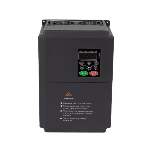
Learn how a VFD for centrifuge duty sets bowl speed and scroll differential. Size the drive, brake the bowl, and commission the pair without nuisance trips.
A VFD for centrifuge duty controls two speeds: how fast the bowl spins, and how fast the scroll turns relative to it. The drive doesn’t create separation. It makes bowl speed and differential adjustable, controls a high-inertia start, and gives the control system a predictable way to stop.
This guide covers industrial separation machines: decanters, basket centrifuges, pushers, and disc stack separators. It is not about lab centrifuges or centrifugal pumps, which share the search results but not the drive requirements.
A fixed-speed machine is simple, but every process change becomes a pulley change or a compromise. A VFD turns that into a recipe, provided the drive is sized for the bowl’s inertia and the stop is designed. If you want a second opinion, send the bowl data to our engineers.
Key Takeaways
- A decanter needs two drives: a bowl drive for separation force, and a scroll drive with a controlled differential.
- Centrifuge motors can draw 800% of full-load current on a direct-on-line start, because the bowl combines high inertia with high speed.
- Size on acceleration torque and stored energy, not running kW. A 4 kg·m² bowl at 3,600 rpm stores 284 kJ.
- Batch machines need 100% braking duty; continuous decanters can share back-drive energy on a common DC bus.
- Specify the braking package with the drive. The YC-5000 lists no built-in brake chopper on its product page.
The bowl is the separation chamber. Its speed sets how hard material presses against the wall, measured as relative centrifugal force.
The relationship is RCF = 1.12 × 10^-5 × rpm² × radius, with the radius in centimeters. A 400 mm bowl at 3,600 rpm produces about 2,900 g at the wall.
A fixed-speed machine gives one g-force, set by the pulley ratio. A VFD gives a range, stored as a recipe per product. One vendor, Kosun, publishes a 0 to 3,900 rpm range on its decanter line; treat that as one product’s range, not a ceiling.
A scroll conveyor turns inside the bowl and pushes settled solids toward the discharge. The difference between scroll and bowl speed is the differential, or delta speed.
Differential speed sets how long solids stay in the bowl. Centrisys explains that a lower differential gives a drier cake, while a higher differential gives a wetter cake and more throughput. If the centrate turns cloudy, the differential is too low.
Zero differential is a fault, not a setting. Bowl and scroll turn together, solids stop moving, and the machine blocks. Centrisys lists incorrect back-drive calibration and wrong scroll position control among the causes, and warns of internal damage if it continues.
The VFD for centrifuge duty holds the value the maker sets.
The video from Centrisys/CNP shows how differential speed moves solids through a decanter.
ABB’s decanter control program describes the standard arrangement. The bowl drive is the master. The scroll drive follows, receiving bowl speed over a fiber-optic link and scaling it by the gearbox and belt ratios before subtracting the delta speed reference (ABB ACS880 Centrifuge Decanter control program).
The motors may be mounted in opposite directions, and belt diameters are entered with signs to match. Get a sign wrong, and the scroll pushes solids the wrong way. ABB also adds a torque window that nudges delta speed when scroll torque rises.
Marta took over the separators at a dairy plant in 2024. Every product change required stopping the line to swap a pulley, and bowl speed drifted as belts wore. One VFD per separator, with a speed recipe on the HMI, removed both problems. Belt wear became a maintenance check, not a quality variable.
A centrifuge is not a pump. It doesn’t unload when flow drops, and it doesn’t stop when you remove power.
Nidec Control Techniques puts it plainly: centrifuges have very high inertia yet require high operational rpm (Nidec). Stored energy rises with the square of speed. A bowl that looks modest on a nameplate can hold a lot of energy at operating speed.
Nidec notes that these motors want to pull 800% or more current until full speed. Across-the-line starting generally won’t work. A direct-on-line start loads the supply, motor, and coupling at once.
The bowl carries the separation load; the scroll carries the conveying load. As solids build, scroll torque rises. If feed changes or differential is too low, the scroll can stall.
A torque limit alone is blunt. Set it low, and the drive trips on a normal cake surge. Set it high, and the gearbox takes the abuse. ABB’s torque window trims delta speed before the machine reaches a trip.
The drive also needs a way out when the scroll is blocked. ABB’s jogging function runs the scroll forward and backward at a preset speed, overriding normal delta speed. Centrisys recommends stopping immediately if zero differential is confirmed, so jogging is a recovery tool, not a running mode.
Denis inherited a decanter retrofit at a municipal wastewater plant in Chile. The new drive tripped on acceleration every morning, and the motor had already been replaced once. The real cause was a short ramp and a conservative torque limit against a bowl with far more inertia than the factory default expected. A longer S-ramp, a motor identification run, and a torque limit set from the measured start curve fixed it.
Basket, pusher, and disc stack machines often use one motor. The bowl and discharge mechanism are linked mechanically, so one drive controls the whole cycle. You get a controlled start, a recipe for each product, and a designed stop. You do not get an independent differential, because there is no independent scroll.
A decanter needs two drives because the bowl and scroll have separate motors. The bowl runs in speed control. The scroll follows bowl speed and applies a delta speed, either fixed or through a torque window.
The link is the critical detail. ABB uses a fiber-optic connection and a dedicated decanter program; other vendors use a PLC, a fieldbus, or an analog reference. The scroll drive must know bowl speed and react within the process response time. A common DC bus often belongs here, because the scroll motor spends much of its time regenerating.
Not every decanter uses a scroll motor. Hydraulic back drives and differential gearboxes are common where very high differential torque is needed or the machine predates modern drives.
A hydraulic drive holds the differential independently and produces high torque at low differential. It also adds a power unit, oil maintenance, and different failure modes. Replacing it is a machine redesign, not an electrical upgrade.
| Architecture | Drives | Differential control | Best fit | Main limit |
|---|---|---|---|---|
| One drive, fixed ratio | 1 | Fixed by mechanics | Basket, pusher, disc stack | No independent differential |
| Two drives, master/follower | 2 | Adjustable, torque-trimmed | Decanter | More cost, link tuning |
| Hydraulic back drive | 1 bowl drive plus hydraulic unit | Hydraulic, high torque | Heavy decanter duty | Oil system, complexity |
Sizing a VFD for centrifuge duty starts with machine data, not a catalog page. Running kW tells you the steady-state draw. It doesn’t tell you what the start, the cake surge, or the stop will demand.
Ask for maximum and normal bowl speed, bowl and scroll inertia, gearbox and belt ratios, motor nameplate, start and stop cycle, process torque, braking time, and ambient conditions. Also ask about hazardous-area classification, motor inverter duty, and scroll overload protection.
Acceleration torque is total reflected inertia times angular acceleration, plus process and friction torque.
Take a bowl with 4 kg·m² of inertia, running to 3,600 rpm in 90 s. Angular speed is 377 rad/s, so acceleration is 4.19 rad/s² and acceleration torque is 16.8 Nm. Add 40 Nm of process torque and 5 Nm of friction, and the shaft needs 62 Nm.
At 3,600 rpm, 62 Nm is about 23 kW. A 30 kW motor is the sensible starting point. A drive with 150% overload for 60 s covers the short peak.
Stored energy is 0.5 × inertia × angular speed squared. For the same 4 kg·m² bowl at 3,600 rpm, that is about 284 kJ.
A controlled stop in 30 seconds needs about 9.5 kW average braking power. The peak is higher, so the resistor or regenerative unit must be rated for the duty cycle, not the average. The drive can be right for the motor and still wrong for the braking package.
The drive can start the bowl many times per hour. The motor often cannot. A self-cooled motor loses cooling as speed falls, and the low-speed part of a long ramp heats it most.
For frequent starts, the answer is usually a separately cooled or inverter-duty motor, not a larger drive. The overload rating protects the drive, not a hot motor.
| Input | Source | What it decides |
|---|---|---|
| Bowl inertia | Maker, or mass and radius | Acceleration torque, stored energy |
| Maximum bowl speed | Nameplate | Motor speed, gearbox ratio, overspeed |
| Acceleration time | Process | Ramp, torque, motor thermal duty |
| Process torque | Maker or measurement | Continuous drive rating |
| Stop time | Process | Braking resistor or regen rating |
| Starts per hour | Schedule | Motor cooling method |
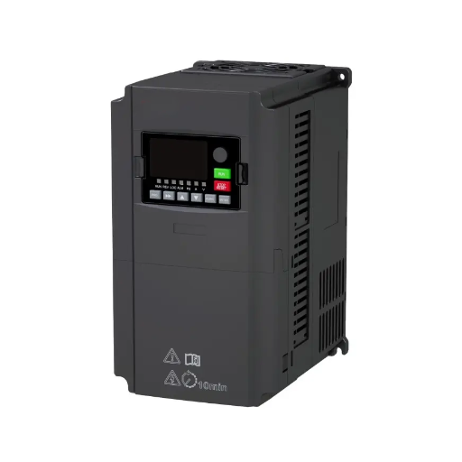
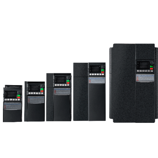
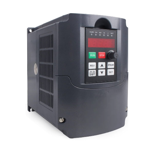
The YC-5000 low-voltage VFD publishes torque control, 200% starting torque at 0.5 Hz, 150% overload for 60 seconds, and 180% for 10 seconds over 0.4 to 500 kW. Those figures cover the start and process surge on many duties. Its product page lists no built-in brake chopper or regenerative unit, so the braking package is specified with the drive for the project.
A centrifuge stop isn’t a normal motor stop. The bowl holds enough energy to keep spinning, and a fast stop pushes it back into the drive.
Nidec describes three paths: a dynamic braking resistor, a common DC bus shared with other drives, or a regenerative front end that returns energy to the line. All three provide braking torque; they differ in where the energy goes.
Bonitron’s centrifuge application note warns that a batch machine’s high-speed stop can exceed the time constant of a braking resistor. That is why 100% braking duty resistors must be specified. An intermittent-duty resistor will overheat an enclosure that wasn’t designed for the heat.
For a continuous decanter, the economics change. The scroll motor regenerates because it resists fluid flow and solids conveyance, and the bowl motor can use that energy over a common DC bus. Bonitron notes that continuous machines are effectively 100% regenerative, and 50 to 100 hp VFDs are common.
The detail on resistor versus common bus versus regenerative front end is in our guide to the four braking energy paths. The centrifuge point is simpler: the bowl stores energy, and the stop must have somewhere to put it. A drive that trips on overvoltage during deceleration is telling you the path is undersized, which is covered in overvoltage on deceleration.
Amina ran a batch basket centrifuge at a chemical plant in 2023. The drive and resistor were both sized on running power. Every high-speed stop dumped the bowl’s energy into an intermittent-duty resistor, and the panel overheated by mid-shift. The fix was a 100% duty resistor, a longer deceleration ramp, and a temperature switch on the enclosure.
A retrofit is sold as a panel change, but it touches the motor, starter, cable, controls, and safety chain. Check these before ordering:
If the drive trips on acceleration after the retrofit, the cause is often the inertia setting or the ramp, not a failed motor. Our guide to overcurrent on acceleration covers the diagnostic order.
Commissioning is where the architecture becomes real. Use the machine maker’s setpoints for the process and the drive maker’s procedure for the electronics.
The machine runs one product at one speed. If the pulley ratio is correct, the process never changes, and the start is not a problem, a fixed-speed machine with a proper starter is cheaper and simpler.
The decanter already has a hydraulic back drive. A hydraulic drive holds a differential with high torque at low speed and does not need a second VFD. Replacing it is a machine redesign, not an electrical upgrade.
The problem is process, not speed. If the cake is wet because feed solids changed, or the centrate is cloudy because the polymer dose is wrong, a new drive will not fix it. Centrisys recommends changing one process variable at a time and waiting at least 10 minutes for the solids to respond.
What does a VFD for centrifuge duty do?
It controls bowl speed and, on a decanter, the speed difference between bowl and scroll. It also controls acceleration and stop, which protect the motor and gearbox on a high-inertia machine.
Can you put a VFD on any centrifuge motor?
Not safely without checking. The motor must tolerate inverter waveforms and the cycle’s cooling duty. A standard motor on a long cable may need a filter, and a self-cooled motor on frequent starts may need ventilation.
Why does a decanter centrifuge need two VFDs?
The bowl and scroll are separate parts with separate motors. The bowl drive sets separation force; the scroll drive follows at a controlled differential to convey solids.
Do I need a braking resistor on a centrifuge VFD?
It depends on the stop. A batch machine with a fast stop usually needs one at 100% braking duty. A continuous decanter may use a common bus or a regenerative front end.
What size VFD for a centrifuge?
Size on motor full-load current, then check acceleration torque, process torque, and braking energy. A drive that matches running kW can still be too small for the start or stop.
A VFD for centrifuge duty controls speed and torque on a machine that stores a lot of energy and punishes assumptions. Bowl speed sets the g-force. Scroll differential sets how solids leave. The drive’s real work is the start, the stop, and the limitin s between.
Start with machine data, size the torque budget and stored energy, choose the braking path for the duty cycle, and prove the trips. On a decanter, treat the bowl and scroll as a pair.
If you are specifying a drive for a centrifuge, send the bowl data to our engineers. We’ll review the motor, cycle, and braking duty before the panel is built. For plant-level context, our wastewater drive guide covers dewatering lines. For duty-cycle sizing, use the RMS method rather than a running-kW shortcut.