Ready to Get Your VFD Solution?
Whether you need a single drive or a complete system, we have the VFD products and engineering support to ensure your project's success.

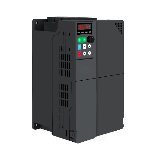
Frequency converter harmonics are limited by one of three rules, and which one applies is decided by two numbers on its nameplate and one fact about the building. Up to 16 A per phase on a public low-voltage supply, the limit is IEC 61000-3-2. From 16 A to 75 A, it is IEC 61000-3-12. Behind a dedicated transformer, none of the three low-voltage rules applies and the whole installation is assessed instead.
That fork is where most discussions of frequency converter harmonics go wrong. Pages begin with how to reduce harmonics, which is the second question. The first is which limit binds you, and until it is answered, every mitigation quote is a guess with a price attached.
Sofia Almeida ran maintenance at a food plant and was told by a supplier that a 5.5 kW converter needed a 5 percent line reactor “to meet 61000-3-2.” The converter drew about 12 A at 400 V and sat behind a dedicated 630 kVA transformer, which put it outside 61000-3-2, 61000-3-12 and 61000-3-4 entirely. The reactor was not a bad purchase. The reason for it was invented.
This guide works through the three routes that govern frequency converter harmonics, the arithmetic that picks between them, and the one case where the answer is nobody’s rule but your own.
Key Takeaways
- Three standards govern frequency converter harmonics, and the boundary between the first two is 16 A per phase: IEC 61000-3-2 below it, IEC 61000-3-12 between 16 A and 75 A.
- The limit changes unit at that boundary. Below 16 A it is absolute amps per harmonic order; above it, order-by-order percentages of a reference current.
- A converter behind a dedicated transformer is outside IEC 61000-3-2, 61000-3-12 and 61000-3-4 completely, so the job becomes an installation assessment rather than a product compliance claim.
- Harmonics from several drives do not add arithmetically, so a harmonic study built on the sum of nameplate distortion overstates the problem and oversizes the fix.
- Put the standard in the specification, not the filter. A filter quote accepted before the limit is identified is a guess with a price.
Buying or specifying a drive and unsure which limit applies? Send the input current, the supply voltage and whether the drive shares a transformer. We will name the standard before anyone quotes a filter. Send us the nameplate and the supply.
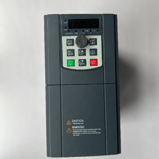
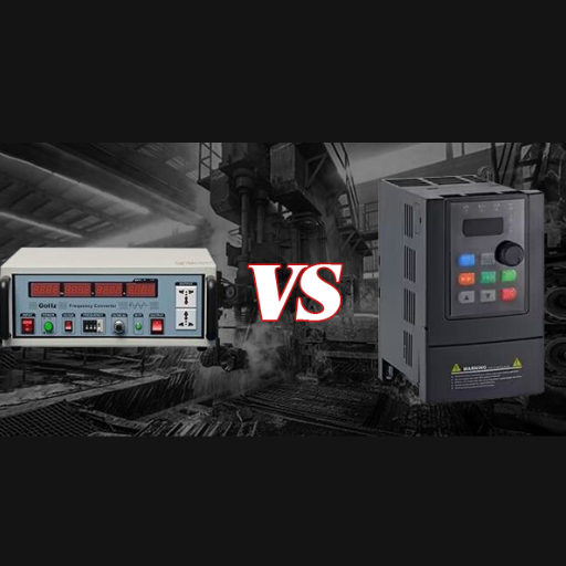
The word “converter” covers a motor drive, a static 50 Hz to 60 Hz unit and a 400 Hz ground power supply. Frequency converter harmonics behave the same way in all three, because the same six-pulse front end produces them. What changes is the rule that limits them, and the rule is set by size and by where the unit is connected.If your project involves running 60 Hz equipment on a 50 Hz grid, our guide to the 50hz to 60hz frequency converter covers how these static units are rated and selected before the harmonic question comes up.
| Input current per phase | Where it is connected | What limits it | Unit of the limit |
|---|---|---|---|
| 16 A or less | Public low-voltage supply | IEC 61000-3-2 | Absolute amps, order by order |
| Above 16 A, up to 75 A | Public low-voltage supply | IEC 61000-3-12 | Percentage of a reference current, orders up to 13, plus THD to order 40 |
| Above 75 A | Public low-voltage supply | IEC 61000-3-4, a technical report | Percentage, similar basis to 61000-3-12 |
| Any current | Not directly on a public low-voltage supply | None of the three. Assess the installation instead | System level |
An absolute amp limit means the same thing at every size, which is why it stops working. A ceiling of 2.3 A on the third harmonic is achievable for a 3 kW converter and impossible for a 75 kW one. Rather than let the rule fail quietly, the standards stop it at 16 A and hand over to a relative limit that scales with the load.
That is the single most useful fact about frequency converter harmonics, and it is also the one that makes the two standards impossible to compare without conversion. A 15 percent figure from IEC 61000-3-12 and a 2.3 A figure from IEC 61000-3-2 measure the same physical quantity in different currencies.
Every route needs the same three facts, and all three are on documents you already have.
Not sure about the third? It is the question that changes the answer most, and it is usually answerable from a single-line diagram. Tell us the supply and we will tell you the route.

A six-pulse drive rectifies the incoming AC, smooths it on a DC link and switches it back to AC. The rectifier draws current in short pulses rather than a smooth wave. The difference between a pulse train and a sine wave is a set of odd harmonics: the 5th and 7th dominant, then the 11th and 13th. Published figures for a six-pulse drive with no choke run from about 35 to 50 percent current THD in normal operation, with the worst cases quoted as high as 120 percent.
Every mitigation technology in common use attacks that pulse train, and the comparison between them has been published widely. This article does not repeat it: the sizing, the cost trade-offs and the difference between THD and TDD are covered in the harmonic mitigation guide for VFDs. Frequency converter harmonics start one step earlier, with the question that guide takes as given.
IEC 61000-3-2 limits the harmonic current that equipment injects into a public low-voltage supply, and it applies to units with an input current of 16 A per phase or less. It sorts equipment into four classes and sets limits in absolute amps for each harmonic order. That makes it easy to check and brutal on anything with a sharp current pulse.
The class that catches a frequency converter is Class A, which is the default for balanced three-phase equipment and for everything not placed in another class. If you need the device-level background first, the AC frequency converter guide covers what the hardware does before it becomes a compliance question.
| Harmonic order | Class A limit |
|---|---|
| 3rd | 2.30 A |
| 5th | 1.14 A |
| 7th | 0.77 A |
| 9th | 0.40 A |
| 11th | 0.33 A |
| 13th | 0.21 A |
The values above are the published Class A limits as reproduced in test reports and regulatory annexes. Check them against IEC 61000-3-2 itself, currently the 2018 edition with amendments through 2024, before quoting them in a tender.
Sixteen amps sounds tiny and is not. On a 400 V three-phase supply it is 11.1 kVA, and a 7.5 kW converter of that size carries a rated input current of roughly 15 to 18 A. The 16 A line therefore falls at about a 7.5 kW drive, which is one of the most common sizes in industry. That is why frequency converter harmonics at the low end are a real question, not a corner case.
On a 230 V single-phase supply, 16 A is 3.7 kVA, and a 2.2 kW single-phase converter is rated around 11 to 12 A. The line there sits near 3 kW.
Both of those conversions depend on a step that is easy to skip. A converter’s nameplate input current is not its power divided by its voltage. A 7.5 kW drive at 400 V computes to 10.8 A on that basis and is rated at 15 to 18 A, because pulsed current and rating margin inflate the figure. Anyone who divides and announces the answer will be roughly 30 to 40 percent low, and will then pick the wrong standard.
Schneider Electric’s application guide states the scope plainly, then adds a sentence that deserves a second look:
“In practice, given the low limit value of the supply current stipulated, very few devices incorporating variable speed drives are subject to the requirements of this standard.”
That claim about frequency converter harmonics is worth testing rather than repeating. The arithmetic above puts the boundary at roughly 7.5 kW three-phase and 3 kW single-phase. Both are common drive sizes, so “very few” is not obviously true on the numbers alone. The sentence may reflect the guide’s own product range, or a view about how drives are usually installed.
Either way, the honest position is a split one. Frequency converter harmonics below 16 A are a product question, and most drives sold sit above that line or behind a transformer. A supplier claiming 61000-3-2 compliance for an industrial drive should be asked which of those two facts applies.
Above 16 A and up to 75 A per phase, IEC 61000-3-12 takes over. It applies to equipment on public low-voltage systems up to 240 V single-phase and 690 V three-phase. Limits are set order by order up to the 13th harmonic, plus a THD limit calculated to order 40.
The change of unit is the point. Where 61000-3-2 gives an amp ceiling, 61000-3-12 gives a percentage of a reference current. The same converter can therefore pass one and fail the other, depending on how the reference is defined.
The standard’s workable shortcut is a ratio. The application guide defines it as the ratio between the short-circuit power of the supply at the connection point and the installed apparent nominal power of the equipment.
“If the equipment complies with the short-circuit ratio (RSCE) between the short-circuit power of the supply system at the connection point (SSC) and its installed apparent nominal power (Sequ), filtering by choke is sufficient to ensure compliance with the limits stipulated.”
In plain terms: on a stiff supply, a choke is enough. On a weak supply, the same converter with the same choke may not be. That is why the ratio, not the drive, is the first thing to establish about frequency converter harmonics.
A compliance claim without an RSCE is a claim without a subject, and that is the most misunderstood part of frequency converter harmonics above 16 A. Two sites can buy the same 30 kW converter and one needs a passive filter while the other does not, because their short-circuit capacities differ by a factor of five.
When a supplier says a converter meets 61000-3-12, ask three follow-ups: at what ratio, with which choke, and evidenced by a type test or by calculation. A datasheet line that says “compliant” without those three is marketing.
IEC 61000-3-4 is a technical report, not a standard, and it recommends rather than requires limits for equipment above 75 A. The distinction matters commercially. A report cannot be written into a contract as a compliance requirement, so above 75 A the specification points at the installation rather than the product. This is where IEEE 519 and its point-of-common-coupling limits usually enter the discussion of frequency converter harmonics.
Here is the sentence that changes most industrial projects, and it is not in any of the mitigation articles because it is not a mitigation question.
“Equipment incorporating PDSs used on a system which is not directly powered by a public low-voltage distribution system is not subject to the requirements of standards IEC/EN 61000-3-2, IEC/EN 61000-3-12 or IEC/EN 61000-3-4.”
A plant with its own 11 kV to 400 V transformer is not on a public low-voltage supply at the drive terminals. The three product standards drop away, and what replaces them is an assessment of the whole installation. That is the third route, and it is where most industrially installed frequency converter harmonics actually live.
Port berths are a common example of this route: a shore power frequency converter feeding docked vessels is typically supplied through its own transformer, so its harmonics are judged at the installation level rather than against a product standard.
The same guide points to the mechanism: “When necessary, the total level of harmonic current emissions generated by the entire installation should be taken into account.” It then names Appendix B4 of IEC 61800-3 as the place to look for an installation strategy.
In practice that means a harmonic study of the bus, covering every non-linear load on it, not just the drives. LED lighting, UPS systems, PV inverters and EV chargers all inject current at the same point. A study that counts only the drives underestimates the voltage distortion, and that is the most common way frequency converter harmonics get under-assessed.
One more sentence from the same page, and it is the practical counterweight to a per-drive reflex:
“It should also be noted that it may be preferable to filter the harmonics of the installation rather than of each of the PDSs individually in order to reduce the risk of resonance.”
That is the difference between a filter catalogue and a design. Forty small filters spread across a bus can interact with its impedance in ways that one filter at the bus does not. That interaction is the resonance risk the guide warns about. For the device-level comparison between a reactor and a filter, see line reactor vs harmonic filter.
Once the assessment moves to the installation, the arithmetic changes. Frequency converter harmonics from several drives on one bus do not add up as their percentages suggest.
If three drives each contribute 30 percent current distortion and their current flows are similar, the arithmetic sum says 90 percent. The arithmetic sum is the worst case and it almost never happens. Frequency converter harmonics do not add that way, because the phase angle of each harmonic differs between drives.
Harmonic summation is the working method: apply an exponent to the sum instead of adding the figures directly. For the 5th harmonic, an exponent around 1.4 is the common engineering assumption. The method applies it to currents rather than percentages.
Raise each individual current to 1.4, add them, then take the result to the power of one over 1.4. The answer lands between the arithmetic sum and a plain root-sum-square, and it is closer to what a measurement finds.
Treat the exponent as a starting assumption, not a law. It depends on drive type, loading and supply impedance, and a study that needs to be defensible replaces it with measured phase angles.
The second correction is diversity. A harmonic study is assessed at a load condition. The condition that matters is drives working hardest together, not every drive at full load at once.
Kwame Boateng inherited exactly this problem at a bottling hall with twelve 7.5 kW drives behind one 400 kVA transformer. A supplier quoted an active filter for each drive. A study of the actual duty found that four lines ran at once and never above 70 percent load. One filter on the bus cleared the point of common coupling limits with room to spare, at roughly a quarter of the per-drive quote.
The instinct is to start with the biggest harmonic source. That instinct is right on a weak supply and wrong on a strong one. What binds the limit is the ratio of available fault current to load current, not the size of the drive.
Forty small drives behind a weak 400 kVA transformer can breach a point-of-common-coupling limit that a single 250 kW drive on a stiff supply never touches. The distortion is also bound up with power factor, since distortion power factor is the part of the measurement that a capacitor bank cannot correct. The VFD power factor guide covers that side of the same measurement.
Every route through frequency converter harmonics ends in the same place, which is a tender document. Five lines remove most of the ambiguity, and each one corresponds to a question the article has already asked.
A specification written this way cannot be answered with the wrong document, because the wrong document cannot fill in line one or line three.
The rectifier at the input draws current in short pulses instead of a smooth sine wave. A six-pulse front end produces characteristic harmonics at the 5th, 7th, 11th and 13th orders. A twelve-pulse or eighteen-pulse front end cancels the lowest of those, in exchange for a larger transformer.
Only to those drawing 16 A per phase or less from a public low-voltage supply. Most industrial drives are above that line or sit behind a dedicated transformer, and one manufacturer’s application guide goes further and says very few drives are caught by it. The floor is low enough that the question is worth asking rather than assuming.
No. On a stiff supply behind a dedicated transformer, a converter can meet the installation limits with no filter at all. On a weak public supply the same unit may need a choke, a passive filter or an active front end. The requirement follows the limit, and the limit follows the supply.
Not arithmetically. Phase-angle differences mean the combined distortion is lower than the sum of the individual figures. An exponent of about 1.4 on the 5th harmonic is the usual way to estimate the real total. A study that adds percentages directly will oversize every filter it specifies.
The ratio between the short-circuit power at the connection point and the installed apparent power of the equipment. When it is met, a choke is enough to stay inside the harmonic current emission limits. When it is not, more than a choke is required, and the ratio is the number that says which.
None of the three low-voltage product standards. Frequency converter harmonics move to a whole-installation assessment, using the harmonic study and the system-level limits. The usual reference point for those is the point of common coupling between the plant and the utility.
Frequency converter harmonics change rule twice on the way from a small drive to a large one. Below 16 A per phase the limit is in absolute amps and the question is a product question. From 16 A to 75 A the limit is relative, and a ratio to the supply decides whether a choke is enough. Above 75 A the document becomes a report, and the specification has to do the work the standard does not.
Behind a dedicated transformer, all three drop away. That is not a loophole and it is not good news: frequency converter harmonics then become your measurement to make, not a supplier’s claim to check. The responsibility moves from the type test to your own harmonic study. That study is the only thing that will balance a filter bill against the limits you actually have to meet.
Three habits settle most of it. Read the input current before the drive rating, because they are different numbers. Ask where the drive is connected before asking what mitigation it needs, and ask for the ratio before accepting a compliance claim. Everything else about frequency converter harmonics is an engineering exercise inside a boundary that those three facts draw.
Send us the input current, the supply and the transformer rating. We will identify the standard, the limit and the point of measurement. We will also tell you whether the filter in the quote is doing anything. Start with the supply.