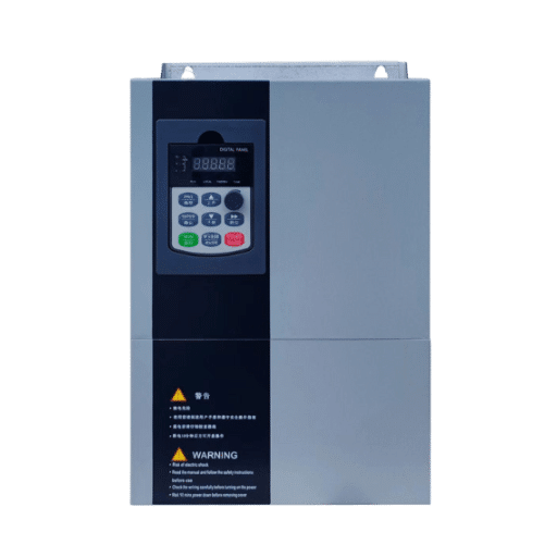
Ready to Get Your VFD Solution?
Whether you need a single drive or a complete system, we have the VFD products and engineering support to ensure your project's success.


How to configure a VFD comes down to ten steps: lock out power, factory reset the drive, enter the five motor nameplate values, set frequency limits, set ramp times, choose a control mode, assign the run command and speed reference, run auto-tuning, then save and test at low speed with the motor uncoupled. Follow that sequence and a standard drive goes from the box to a running motor in about 15 minutes.
Daniel, a maintenance lead at a food processing plant in Penang, learned why order matters. In February, he wired a new 7.5 kW drive for a transfer pump, skipped the factory reset, and entered motor current from memory instead of the nameplate. The drive tripped on overcurrent three times before lunch. A ten-minute reset and correct nameplate entry fixed everything. The drive was never the problem. The configuration sequence was.
This guide walks you through the same ten steps our commissioning engineers use on standard three-phase induction motors with keypad or terminal control. If you are setting up PID loops, fieldbus communication, or vector control for demanding loads, our complete VFD configuration and commissioning guide covers those advanced paths in depth.
Key Takeaways
- Always start with a factory reset and enter motor nameplate data exactly as printed. Wrong full load amps (FLA) is the number one cause of nuisance trips.
- Set minimum frequency at 10 to 15 Hz for standard fan-cooled motors, or the motor can overheat at low speed.
- Match ramp times to the load: pumps start around 5 to 15 seconds, fans 10 to 30 seconds, high-inertia loads 10 to 60 seconds.
- Five parameters (control mode, motor FLA, accel time, decel time, max frequency) cover roughly 80% of installations.
- Test uncoupled at low speed first, verify rotation direction, then connect the load.

Before you touch the keypad, gather five values from the motor nameplate: rated voltage, rated current (FLA), rated frequency, rated speed in RPM, and rated power in kW or HP. These five numbers drive almost every protection and control calculation inside the VFD, so copy them exactly.
You also need three things confirmed: that the wiring is complete and checked, that you know the load type (pump, fan, conveyor, or other), and that the drive manual is open to its parameter list. Motor nameplates follow international standards such as NEMA MG 1, so the same five values appear on virtually every industrial motor.
Working with a drive from our range? Our engineers can walk you through the first-time setup for your specific application. Talk to the Shandong Electric team before you energize.
Here is the complete sequence at a glance. Each step is explained in detail below.

Kill the supply and apply lockout/tagout per OSHA hazardous energy control requirements. Then wait 5 to 10 minutes before touching any terminal. The DC bus capacitors inside a 400 V class drive can hold 500 to 800 V DC after power-down.
What goes wrong if you skip it: electric shock, and a damaged drive if you wire into live terminals.
Energize the drive with the motor connected but not running. Find the factory reset or parameter initialization function and execute it. This clears leftover settings from testing, previous installations, or a donor drive.
What goes wrong if you skip it: hidden parameters from an unknown state override your new settings, and you spend hours chasing faults that were programmed in by someone else.
Enter rated voltage, FLA, frequency, speed, and power exactly as printed. Never substitute supply voltage for motor voltage, and never estimate current from breaker size or horsepower. If the nameplate is worn or missing, our guide to VFD motor nameplate parameters explains how to recover each value.
What goes wrong if you skip it: the drive loses accurate thermal protection, and you get the overcurrent trip pattern Daniel hit in Penang.
Set the maximum frequency to the motor nameplate value, typically 50 or 60 Hz, unless the driven equipment is rated for overspeed. Set the minimum frequency to 10 to 15 Hz for a standard totally enclosed fan-cooled motor.
What goes wrong if you skip it: below about 10 Hz, the shaft-mounted cooling fan moves too little air and the motor overheats even under light load. Above the mechanical limit, bearings and driven equipment wear out early.
Ramp times control how aggressively the drive changes speed. Use these starting points and adjust from there:
| Load Type | Acceleration | Deceleration |
|---|---|---|
| Centrifugal pump | 5 to 15 s | 10 to 30 s |
| Centrifugal fan | 10 to 30 s | 20 to 40 s |
| Conveyor | 3 to 10 s | 3 to 10 s |
| High-inertia load | 10 to 60 s | 20 to 60 s |
What goes wrong if you skip it: acceleration that is too short causes overcurrent trips; deceleration that is too short pushes regenerative energy into the DC bus and causes overvoltage trips. For the full sizing math, see our VFD ramp settings article.
Start with V/Hz control. It is simple, efficient, and correct for the majority of pump, fan, and general machinery applications. Move to sensorless vector control only when you need strong torque at low speed, such as conveyors starting under load. Our comparison of VFD control modes explains when each mode earns its complexity.
What goes wrong if you skip it: choosing vector control without tuning gives you worse performance than V/Hz, plus tuning headaches you did not need.
Tell the drive where start and stop commands come from: the keypad, external control terminals, or a fieldbus network. For a first-time setup, keypad control is the safest choice because it removes external wiring from the equation.
What goes wrong if you skip it: a mismatched command source is one of the top reasons a VFD is not running even though everything looks correct. The drive waits for a signal that will never arrive.
Tell the drive where the speed command comes from: keypad entry, an external potentiometer, a 0 to 10 V signal, or a 4 to 20 mA analog input. For first-time setup, use the keypad and set a fixed test frequency.
What goes wrong if you skip it: if the reference points to an unwired analog input, the drive reads zero speed and the motor never turns, which looks exactly like a hardware failure.
Auto-tuning measures the motor’s stator resistance and inductance so the drive can model it accurately. Run a static tune with the motor connected and stopped. It takes under a minute on most drives. Our VFD auto-tuning guide covers static versus dynamic tuning and when each matters.
What goes wrong if you skip it: field experience suggests roughly 80% of engineers skip this step, then wonder why vector control performs poorly or slip compensation behaves strangely.
Save the parameter set, then run a no-load test with the motor uncoupled at 5 to 10 Hz. Check three things: rotation direction, running current against nameplate FLA, and abnormal noise or vibration. Reverse any two motor leads at the drive output if the direction is wrong, then shut down and couple the load.
What goes wrong if you skip it: a pump running backward moves almost no flow and can dry-run to seal failure while the motor current looks perfectly normal.

Maria, a contractor who commissions water booster systems across Manila, keeps a laminated card in her toolbox with just five parameter groups. On a typical residential booster job she touches nothing else, and her drives run for years without a callback. Here is her card:
| Parameter Group | What to Set | Typical Starting Value | When to Change It |
|---|---|---|---|
| Control mode | V/Hz | V/Hz | Low-speed torque problems |
| Motor FLA | Nameplate current | Exact nameplate value | Never estimate |
| Acceleration time | Ramp up | 10 s | Overcurrent trips on start |
| Deceleration time | Ramp down | 20 s | Overvoltage trips on stop |
| Maximum frequency | Speed ceiling | 50 or 60 Hz | Equipment rated for overspeed |
If your application runs correctly on these five, stop there. Every additional parameter you change is one more thing to document, back up, and troubleshoot later.
The ten steps above handle a standard motor on keypad control. Four situations call for deeper VFD parameter configuration:
Each of those links goes to a dedicated guide, so you only learn what your application actually needs.
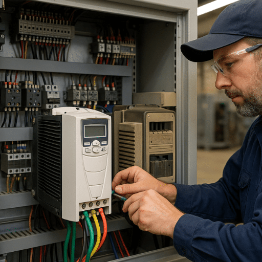
Most first-run faults trace back to five configuration errors:
Notice that none of these are hardware problems. They are sequence problems, and they are exactly why a disciplined ten-step process beats experience alone.
These are the questions our commissioning engineers hear most often about how to configure VFD systems for the first time.
A standard setup takes 10 to 20 minutes once wiring is complete. Add time for auto-tuning and the uncoupled test run. Complex setups with PID loops or fieldbus communication can take one to two hours.
You can complete basic setup without one, since the ten steps above are manufacturer-agnostic. You will need the manual for parameter numbers, factory reset procedure, and any advanced functions. Most manufacturers publish manuals online.
Run it whenever the motor or drive changes, and always before using vector control. For simple V/Hz applications, it is optional but still recommended, because it improves slip compensation and current accuracy.
Too high and the drive loses thermal protection, so the motor can overheat without tripping. Too low and the drive trips on overload during normal operation. Always use the exact nameplate FLA.
Only if the motor, load, and wiring are identical. Motor nameplate values and ramp times are motor-specific, so copying between different machines is one of the most common commissioning errors.
Configuring a VFD is not complicated once the sequence is clear: reset, nameplate, limits, ramps, control mode, command and reference, tune, then test uncoupled. Daniel’s overcurrent trips and every mistake in the list above came from skipping steps, not from bad hardware.
Follow the ten steps, start with the five core parameters, and only go deeper when your application demands it. For advanced setups, our complete VFD configuration guide picks up where this quick-start ends.
Need a drive that is straightforward to configure and backed by real engineers? The Shandong Electric VFD range covers 0.1 kW to 53,000 kW with commissioning support from selection through first run. Send us your motor nameplate and application, and we will recommend the right drive and starting parameters.