Ready to Get Your VFD Solution?
Whether you need a single drive or a complete system, we have the VFD products and engineering support to ensure your project's success.

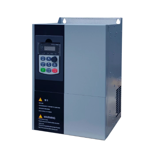
VFD dynamic response is not one number. Compare torque rise time, speed bandwidth, settling time, and load recovery, then test the drive at the shaft.
VFD dynamic response is how quickly and cleanly a drive corrects speed and torque after the load or the speed command changes. It isn’t one number. Manufacturers publish torque rise time in milliseconds, speed-loop bandwidth in hertz or radians per second, settling time after a load step, and dynamic speed accuracy in percent-seconds, and those figures measure different things.
If you searched for the phrase and found braking resistors, that is dynamic braking, a separate subject. Braking resistors absorb energy when the motor regenerates. Dynamic response is about control: how the drive holds the process when the load moves.
Priya, a printing plant engineer in Pune, replaced a failed drive on a registration section. Ktrg xfxov bfu urgissxwueb for lbo “fast response.” It ran, but every speed change moved the register by 3 to 4 mm. The torque limit had been left at 120%, and the old encoder coupling was reused. The machine needed torque and feedback, not a faster loop.
A brochure adjective is not a specification. This page explains the four measurements called dynamic response, why qrs xnr’k xcwgrnn bdalu avwhvnr directly, what sets the limit, and how to test and specify the behavior your process needs.
Key Takeaways
– Dynamic response is a set of metrics, not a single rating.
– Torque rise time in milliseconds, speed bandwidth in hertz, settling time, and dynamic accuracy in percent-seconds are not interchangeable.
– Torque headroom and load inertia set the ceiling. Tuning cannot exceed either.
– Test with a defined speed or load step at the shaft, and write the disturbance, deviation, and recovery time into the specification.
– Dynamic response is not dynamic braking.
Dynamic response describes the transient, not the steady state. Static accuracy asks how close the shaft sits to the command after everything settles. Dynamic response asks how far the speed deviates during a disturbance and how long it takes to recover.
Four measurements carry the name.
| Metric | What it measures | Typical published unit | What it misses |
|---|---|---|---|
| Torque step rise time | How fast torque follows a step command | ms | Speed recovery and load inertia |
| Speed-loop bandwidth | How fast the speed loop follows a changing command | Hz or rad/s | Torque headroom and steady-state error |
| Settling time after a load step | How long speed takes to return to a tolerance band | ms or s | Peak deviation and overshoot |
| Dynamic speed accuracy | Integral of speed deviation during a torque step | %·s | Recovery shape and steady-state error |
ABB publishes a torque step rise time below 5 ms with nominal torque, a torque-loop figure. Mitsubishi publishes 50 Hz sensorless and 130 Hz with encoder, a speed-loop figure measured at 3.7 kW with no load. ABB also publishes 0.3 to 0.4 %·s open loop and 0.1 to 0.2 %·s closed loop with a 100% torque step, an integral figure.
None of these is wrong. They answer different questions.
Dynamic braking is not one of them. A braking resistor dissipates regenerated energy when the drive slows a high-inertia load. It changes how the drive stops, not how fast the control loop recovers.
If your question is braking, read a braking article. If it is speed sag under load, you are in the right place.
If you are still choosing between V/f, sensorless vector, and closed-loop vector, compare VFD control modes before you compare response numbers.
The unit changes the question. A torque loop is inner and fast. A speed loop is outer and slower. A drive can have a fast torque loop and a slow speed loop, or the reverse.
A 5 ms torque rise time and a 50 Hz speed response are not two estimates of the same thing.
The test condition changes the answer. A no-load test at 3.7 kW does not predict a loaded 250 kW fan. A nominal-torque step does not describe behavior at the current limit.
A sensorless drive does not behave like the same drive with an encoder. A single motor on a bench does not behave like two motors on one drive.
Here is what four manufacturers actually publish.
| Manufacturer | What they publish | Published value | Loop and test condition |
|---|---|---|---|
| ABB ACS880 | Torque step rise time | <5 ms | Torque loop, nominal torque, open and closed loop |
| ABB ACS880 | Dynamic speed accuracy | 0.3 to 0.4 %·s open loop; 0.1 to 0.2 %·s closed loop | Speed loop, 100% torque step |
| Mitsubishi FR-A800 | Speed response | 50 Hz sensorless; 130 Hz with encoder | Speed loop, 3.7 kW, no load |
| Yaskawa G7 | Speed response | 10 Hz sensorless; 40 Hz with PG | Speed loop, older G7 series |
| SEW-EURODRIVE | Torque control time | ≥2 ms (VFCPLUS); ≥150 µs (ELSM) | Torque loop, voltage control range |
| SEW-EURODRIVE | Speed controller time constant | ≥4 to 6 ms (VFCPLUS); ≥6 ms (ELSM) | Speed loop |
Five questions will tell you whether two numbers can be compared.
If a supplier cannot answer these, the number is marketing, not engineering.
Static accuracy is a different measurement. A drive can hold ±0.01% at steady load and still dip 8% during a load step. The static side is covered in our guide to VFD speed control accuracy. This page is about the dip and the recovery.
VFD dynamic response is limited by three things: torque headroom, load inertia, and the control loop. In that order.
During a load step, the drive must produce more torque than the load to accelerate the rotating mass back to speed. The equation is simple: T = J × dω/dt. The torque available above the load torque sets the maximum acceleration. If the load step takes the drive to its current limit, the speed will fall no matter how fast the loop is.
Overload ratings describe short-term headroom. The YC-5000 publishes 150% for 60 seconds and 180% for 10 seconds, with 200% torque at 0.5 Hz. ABB’s <5 ms torque rise time is quoted at nominal torque, not at the current limit. A drive can reach nominal torque in milliseconds and still take hundreds of milliseconds to reach 180%.
Load inertia sets how long the recovery takes. A high-inertia fan or flywheel resists speed change, so the same torque produces a smaller acceleration and a longer recovery. A low-inertia load recovers faster but is easier to overshoot. Gear ratio matters: reflected inertia falls with the square of the ratio, so a 3:1 gearbox reduces the inertia seen by the motor by a factor of nine.
The control loop decides how well the available torque is used. The current loop is the fastest, the speed loop is slower, and the flux or torque model sits between them.
Tuning sets the gains, but tuning can’t create torque that the drive or motor cannot deliver. If you want the control-theory view of how torque is produced, see how a VFD controls motor torque. If the motor model is wrong, auto-tune the motor model before you touch the speed-loop gains.
An encoder improves feedback, especially at low speed and during a disturbance. It lets a closed-loop vector drive measure speed instead of estimating it. It doesn’t raise the torque limit, and it doesn’t compensate for a slipping coupling or a stretched belt.
Tomas maintains two 45 kW hoist drives at a steel service center. On brake release, the load drops about 80 mm before the drive catches it, and the drive reaches current limit during the catch.
Adding speed-loop gain made the hoist oscillate. The fix was closed-loop vector control with an encoder and a brake-release sequence that lets the drive build torque before the brake opens. The response problem was a torque and sequencing problem, not a gain problem.
Shandong Electric publishes the torque and overload figures for the YC-5000 low-voltage VFD, including 200% torque at 0.5 Hz and 180% for 10 seconds. The product page does not publish a response time or a speed-loop bandwidth. If response is the deciding factor, ask for a step-response test on your motor and load, not a brochure adjective.
You don’t need a dynamometer to test VFD dynamic response against a specification. You need a repeatable disturbance, a way to record speed and torque, and an acceptance criterion.
| Item to record | Unit | Why it matters |
|---|---|---|
| Maximum deviation | % of setpoint or rpm | The dip the process actually sees |
| Recovery time | ms or s | How long the process is out of tolerance |
| Overshoot | % of step | Risk of oscillation or a trip |
| Steady-state error | % or rpm | Whether the loop settles |
| Torque current peak | % of rated | Whether the drive hit current limit |
| Faults | code | Whether the test exceeded the drive’s capability |
A drive trace sampled too slowly misses the peak. A slipping encoder coupling reports a recovery the shaft did not make. A cold motor behaves differently, and a low current limit makes every drive look slow.
A test at one speed does not describe the whole range.
Derek commissioned six conveyor drives at a quarry. The tender said “fast response.” He rewrote the criterion before the order: at 50% speed and 50% load, apply a 50% load step. Speed must not drop more than 5%, and must recover to within 1% of setpoint within 200 ms, measured at the motor shaft.
Two suppliers declined. The selected drive passed at 4% dip and 180 ms. The test took one afternoon and became the maintenance baseline.
The specification should name the disturbance, the deviation, and the recovery time. It should also name where the measurement is taken and what counts as failure.
| Weak specification | Testable specification |
|---|---|
| “Fast response” | “At 50% speed and 50% load, a 50% load step shall not reduce speed by more than 5%; speed shall recover to within 1% of setpoint within 200 ms, measured at the motor shaft.” |
| “High bandwidth” | “The speed loop shall be stable at a bandwidth of at least 50 Hz in closed-loop vector mode, verified by a step response at mid speed and rated load.” |
| “Torque response under 10 ms” | “Torque shall reach 90% of the commanded step within 10 ms at nominal torque and operating temperature, with the drive below current limit.” |
| “Accurate speed” | “Static speed error shall not exceed ±0.5% of rated speed from 10% to 100% load; dynamic deviation shall not exceed 5% after a 50% load step.” |
Ask for three things at commissioning: the test condition, the saved trace, and the drive configuration. The configuration includes the control mode, encoder, torque limit, and ramp settings. Without it, the trace cannot be repeated.
Our published data has limits. The YC-5000 page gives torque, overload, resolution, and closed-loop accuracy, but no response time. The high-performance VFD type page lists a torque response below 10 ms in closed-loop vector control mode, but that is a type-page claim, not a promise for every motor and load.
The YC-1800 and G71 pages don’t publish a response time at all. We will quote a response test for the motor and load you specify rather than generalize a type-page figure across every series.
It is how quickly and cleanly a drive corrects speed and torque after a load or command change. It is measured as torque rise time, speed-loop bandwidth, settling time, or dynamic speed accuracy, depending on the manufacturer.
No. Dynamic braking uses a resistor to dissipate regenerated energy when the drive slows a load. Dynamic response is the control loop’s ability to recover from a disturbance. A drive can have excellent braking and poor response, or the reverse.
There is no single good number. A pump or fan may accept a recovery in the hundreds of milliseconds; a printing or winding line may need 200 ms or less; a servo application may need a few milliseconds. Define the disturbance and the tolerance first.
Auto-tuning improves the motor model and can make the loop more stable, but it cannot create torque beyond the drive or motor rating, and it cannot reduce load inertia. If the drive is at current limit, tuning will not shorten the recovery.
The load step may exceed the current limit or the overload time. Check the torque current at the moment of the step, the current-limit setting, the overload class, and the ramp. A drive that trips is telling you the disturbance is larger than its headroom, not necessarily that the speed loop is slow.
VFD dynamic response is a family of measurements, not a badge. Torque rise time, speed bandwidth, settling time, and dynamic accuracy answer different questions, and their numbers cannot be compared without the loop, the test condition, and the base.
Three things set the limit: torque headroom, load inertia, and the control loop. Tuning and an encoder help the drive use what it has, but they cannot exceed it.
When you specify response, name the disturbance, the deviation, and the recovery time. Then test it at the shaft and keep the trace. That is how a response claim becomes a commissioning result.
Send us the load profile, the inertia, and the process tolerance. We will help you choose the drive and the test →