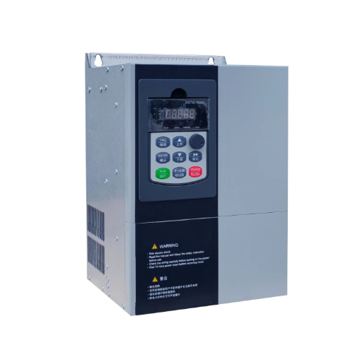
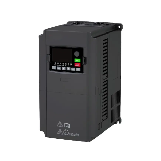
Ready to Get Your VFD Solution?
Whether you need a single drive or a complete system, we have the VFD products and engineering support to ensure your project's success.

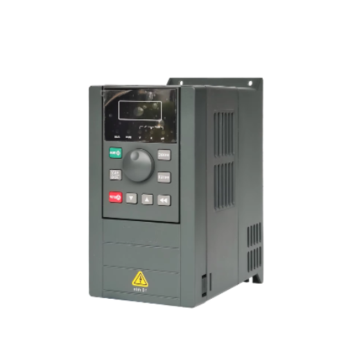
A VFD can run a permanent magnet motor, but only if it has a synchronous motor control mode and a way of establishing rotor position: back-EMF estimation at speed, high-frequency injection at standstill, or an encoder. A drive without one of those three will not start the motor reliably, whatever its nameplate says.
The rest of this page is how to check whether the drive in front of you has it. Choosing a VFD for permanent magnet motor duty comes down to those three things, and none appear in the kilowatt column.
In 2025, a maintenance engineer at a food plant near Weifang, call them Zhang Lei, replaced three 30 kW induction motors with permanent magnet motors on a conveyor line. The efficiency figures were real, and so was the drop in the electricity bill. The existing general-purpose drives stayed, because they were two years old and nothing on the motor nameplate said they wouldn’t work.
Two of the three ran at full speed and looked fine. Under a loaded start, one tripped on overcurrent and the other hunted for four seconds before it did the same. Neither drive had a menu for the motor now bolted to it.
You already know a PM motor is efficient. The harder question is whether the drive can hold it in step, and that answer lives in a parameter list rather than a brochure. This article gives you the three levels of PM support, the six things to check on a datasheet, and the settings behind most of the failures.
Key Takeaways
- A VFD needs a synchronous motor control mode before anything else. A general-purpose drive running V/Hz won’t hold a permanent magnet motor under load.
- Rotor position comes from three sources: back-EMF above a threshold speed, high-frequency injection at standstill, or an encoder. A drive with none of them can’t start a loaded motor.
- High-frequency injection needs rotor saliency, so an interior PM motor is a better candidate than a surface-mount motor with the same nameplate.
- Demagnetisation is a drive setting as much as a motor event. The current limit and the rotor temperature decide it, not the magnet alone.
- The check takes five minutes: find the PM control mode, the minimum sensorless speed, the injection option, the autotune, the encoder card and the current limit in the manual’s parameter list.
Tell us the motor model and the drive, and our engineers will tell you whether the pair will start.
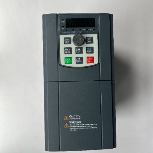
A permanent magnet synchronous motor (PMSM) puts magnets on or inside the rotor. There is no rotor winding and no induced rotor current, so there is no slip. The Schneider Electric FAQ on exactly this question puts it plainly: an induction motor needs slip to induce rotor flux, while a PMSM does not slip at all, and its speed follows the frequency exactly.
That single difference changes what the drive has to do, in three ways.
The rotor flux is always there. An induction motor’s rotor field is produced by current the drive controls. A PM motor’s field is produced by the magnets, whether or not the drive is powered. Spin the shaft by hand and there is voltage at the terminals. That is a maintenance hazard, and a control constraint: the drive can’t switch the field off and build it again.
The terminal voltage rises with speed. Back-EMF is proportional to speed. Above the motor’s base speed the generated voltage approaches what the inverter can supply, so the drive has to weaken the field with negative d-axis current to go faster. “PM motors run at any speed” isn’t true. They run until the inverter runs out of volts.
There is no slip to recover with. An induction motor overloaded past breakdown torque slows down, and when the load drops it picks the speed back up. A PM motor that loses synchronism has no mechanism to recover with. It stalls or the drive trips, and it doesn’t coast back into step.
Efficiency is why most people are reading this page. PM motors are usually more efficient than induction motors of the same rating. That comparison has its own numbers, and it isn’t what decides whether your drive works.
Two rotor types matter for everything that follows. A surface-mounted permanent magnet motor (SPM) glues the magnets to the rotor surface. An interior permanent magnet motor (IPM) buries them inside the rotor. The difference looks mechanical and behaves electrically, which is where the position question begins.
If the motor isn’t an induction motor at all, our guide to covers the other families.
Choosing a VFD for permanent magnet motor duty isn’t a yes or no question. Drives come in three levels, and the level decides what the motor does at its hardest moment.
Three levels of PM support, and the one column buyers forget to ask about.
| Level | What the manual shows | Starts a loaded motor from standstill? | Encoder needed? | Typical use |
|---|---|---|---|---|
| 1. Induction only | V/Hz, sensorless vector, closed-loop vector, all for induction | No | Not applicable | A drive that predates the motor |
| 2. Back-EMF sensorless | A PM or synchronous menu, plus a minimum speed or a sensorless PM note | No | No | Compressors, fans and pumps that start unloaded |
| 3. Injection or encoder | A PM menu plus an injection parameter, or a closed-loop PM mode | Yes | Only for closed-loop control | Conveyors, hoists, extruders, anything that starts loaded |
The datasheet rarely names the level. It says “V/F and sensorless vector control”, which is true of induction motors and incomplete about yours. The level is in the manual’s parameter list, and that document is published before you buy.
Most drives sold for pump and fan duty sit at level 1 or level 2. That isn’t a defect, because a centrifugal pump starts unloaded. It becomes one the day someone swaps in a PM motor and expects a loaded start.
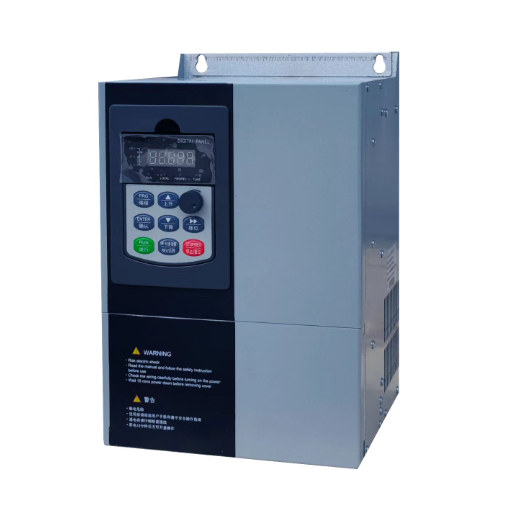
A synchronous motor needs the stator field aligned with the rotor before it produces useful torque. Get it wrong and the torque is weak or absent. A drive has three ways to find that angle.
The magnets induce a voltage in the stator windings as they pass, and that voltage carries the rotor angle. Above a threshold speed the signal is large enough to read. At standstill it is zero, so this method has nothing to work with at the moment a loaded motor needs the most torque.
The threshold isn’t fixed. It depends on the drive, the motor and the load, and the manual may state one for a typical case. covers the estimation methods in more depth than a datasheet will.
The drive injects a small high-frequency voltage on top of the fundamental and watches the current response. That response depends on inductance, and inductance depends on rotor angle when the rotor is salient, meaning the d-axis and q-axis inductances differ.
An IPM motor buries the magnets in iron and is usually salient enough to read. A surface-mounted rotor is closer to uniform, so the method gets weak. treats that saliency as the degree of freedom the control uses, which is the same point from the design side.
A drive that lists injection as available is telling you it has the method. It isn’t telling you the method will work on the motor you have.
The costs are real. Injection adds audible noise at the carrier frequency, some torque ripple, and a tuning step that needs the actual motor constants rather than catalogue values.
A shaft encoder gives position directly, at any speed, with no estimation. It is the answer when breakaway torque is high, when the load is a hoist that cannot be allowed to drop, or when constant torque is needed below the speed where back-EMF estimation works. It costs a feedback card, a cable and installation time.
Without any of the three, the drive is guessing. A guess that holds at light load becomes a synchronism loss under load, which shows up as a stall or an overcurrent trip.
Six items separate a VFD for permanent magnet motor duty from one that can only spin the motor. Ask for each in writing, and treat an adjective as a no.
Item 6 is the one buyers miss. Overcurrent protection in an induction drive is written mainly to protect the drive. On a PM motor it also protects the magnet, and the setting has to be right for the motor, not just adequate for the module.
Five minutes with a manual answers all six. The selection process around them is a longer conversation, and our guide to covers it end to end.
We aren’t going to tell you our own range passes this list until our engineering team confirms the parameter menu for the series you are considering. Ask for that page with the quote, from us or from anyone. A checklist that only applies to competitors isn’t a checklist.
Ask for the parameter list, not the brochure line.
Most PM motor VFD commissioning failures aren’t hardware faults. They are induction settings left in place, each with a signature you can recognise.
A commissioning engineer in Handan spent a day in 2024 on a 45 kW PM motor that tripped on overcurrent every time the line started loaded. The drive had been autotuned on the bench, then coupled to the gearbox, then started. The inductance it stored was measured with the gearbox locking the shaft.
Re-running the identification with the coupling open took six minutes. Finding that out took a day, two motor removals and one call to the motor supplier. The parameter was never wrong. The conditions the parameter was measured under were.
If the trips arrive during acceleration rather than at start, the problem may be the ramp rather than the control mode, and our guide to separates the two cases.
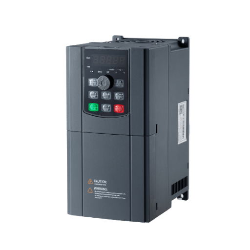
The retrofit is the most common form of the VFD for permanent magnet motor question, and it has a clean answer in three checks.
First, the control mode. Open the manual and look for a synchronous or PM menu. If it isn’t there, stop. No parameter change creates a control mode the firmware doesn’t contain.
Second, the firmware version. A manual printed three years ago may not describe the version on your wall, and PM support is one of the functions that arrives in an update. Read the version off the keypad and check it against the release notes.
Third, the encoder option. If the motor is a surface-mount type or the load starts hard, the answer may be closed loop. A drive without that feedback option can’t take that route, whatever its open-loop behaviour.
A general-purpose drive can usually run a PM motor above its sensorless threshold on a load that starts easily. It usually can’t start a loaded conveyor, hold a hoist, or run at low speed on constant torque.
If you need a different drive, buy the one with the menu. If the application is a positioning problem rather than a speed problem, a servo drive is the honest comparison, and our guide covers where that line sits. On the drive side, our guide to the explains what the extra cost buys.
Yes. A VFD for synchronous motor duty needs two things: a synchronous control mode and a position source. A drive with both can run the motor above its sensorless threshold, or from standstill with an encoder. A drive with neither won’t hold synchronism once the load rises.
There is no best model, because the answer depends on your rotor and load. The best VFD for a permanent magnet motor is the cheapest one whose manual lists a PM control mode, a position source that suits your rotor, and a current limit you can set below the magnet’s limit.
Because the drive has no position signal at low speed. Back-EMF estimation is weak or absent below its threshold, and without injection or an encoder the drive can’t keep the stator field aligned with the rotor. It stalls or trips rather than producing torque.
Not always. A drive with high-frequency injection can start and hold an interior PM motor without one. You need an encoder when the rotor has too little saliency for injection, when breakaway torque is high, or when the load must hold position or speed near zero.
The drive cares about saliency. An IPM motor has a large inductance difference between its axes, which is what injection methods read. A surface-mount motor is closer to uniform, so injection works poorly and an encoder is more often the answer.
You can often make it spin at a fixed speed with no load. It isn’t usable under load, because V/Hz control assumes the motor can slip and a PM motor can’t. It is a test-bench behaviour, not an application.
The motor itself usually survives, because the event is short. The risk is the current that flows during the loss and how long the drive takes to trip. Repeated synchronism loss, or a current limit set too high, is what turns a nuisance trip into a demagnetised rotor.
A VFD for permanent magnet motor duty isn’t a premium tier. It is a control mode, a position source and a current limit, and all three are written down before you pay.
The three levels are the short version. A drive with no PM mode can’t be talked into one. A drive with back-EMF estimation runs, but not from a loaded standstill. A drive with injection or an encoder does the whole job, and it is the only level that starts the loads people actually retrofit.
The motor’s efficiency is on the brochure. The drive’s ability to start that motor is in the parameter list, and the six checks take five minutes with the manual in front of you.