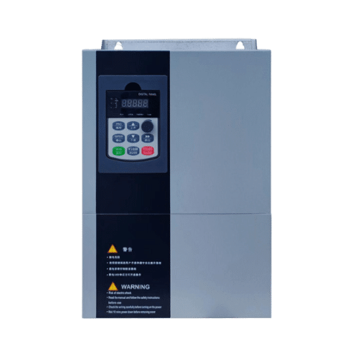
Ready to Get Your VFD Solution?
Whether you need a single drive or a complete system, we have the VFD products and engineering support to ensure your project's success.


A VFD raises displacement power factor to roughly 0.95-0.98 at any motor speed, but harmonic distortion holds power factor lower, typically 0.89-0.95 on a standard 6-pulse drive. That gap between the two numbers is where most of the confusion about VFD power factor lives, and it is where utility penalties and failed capacitor banks come from.
Here is the part almost nobody tells you. The capacitor bank you installed years ago to fix your plant’s power factor may need to come OUT when VFDs go in. Leave it connected to a bus full of drive harmonics and it can resonate, overheat, and fail violently. We have seen capacitor cans rupture within months of a VFD retrofit that nobody thought to involve the power factor correction equipment in.
We build variable frequency drives, and power factor questions come up in nearly every specification we review. This guide gives you the displacement versus distortion distinction with real numbers, power factor by drive topology, the capacitor bank rules, and the values to write into a procurement spec. Every number is labeled as displacement or true power factor, because mixing the two is the single most common error in everything written on this topic.If you would like a comprehensive overview of variable frequency drives (VFDs), please refer to our guide on the benefits of VFDs.
Key Takeaways
- A VFD improves displacement power factor to 0.95-0.98 across the full speed range because its DC bus, not the supply, delivers the motor’s magnetizing current.
- True power factor is lower than displacement power factor because of harmonic currents: a 6-pulse drive at 0.98 displacement PF and 45% THDi delivers only ~0.89 true PF.
- True PF = cos θ / √(1 + THDi²). No spec or utility bill should be evaluated without knowing which power factor it references.
- Never connect standard power factor correction capacitors to a bus feeding VFDs; harmonic resonance can destroy them. Use detuned banks, and never put capacitors at a VFD’s output terminals.
- Specification minimums used in industry: ≥0.95 true PF at rated load for 6-pulse drives, ≥0.98 for 18-pulse, displacement PF ≥0.98 at all speeds.

A standard 6-pulse VFD has a displacement power factor of 0.95-0.98 and a true power factor of roughly 0.89-0.95 at rated load, depending on whether a line reactor or DC choke is fitted. Multi-pulse and active front end drives push true power factor to 0.98 or higher. The motor-side power factor between drive and motor stays at the motor’s natural 0.7-0.85.
Two different “power factors” exist because a VFD draws current in pulses rather than a sine wave. The table below shows the VFD power factor and current distortion (THDi) each common drive topology actually delivers.
| Drive Topology | Typical THDi | Displacement PF | True PF (approx.) |
|---|---|---|---|
| 6-pulse, no reactor | 90-120% | 0.95-0.98 | 0.75-0.85 |
| 6-pulse + 3-5% line reactor or DC choke | 35-45% | 0.95-0.98 | 0.89-0.94 |
| 12-pulse | 10-12% | 0.95-0.98 | ~0.95 |
| 18-pulse | 5-6% | 0.95-0.98 | 0.98 |
| Active front end (AFE) | 3-5% | Controllable, ~1.0 | 0.98+ |
| 6-pulse + passive harmonic filter | 5-13% | 0.95-0.98 (can go leading at light load) | 0.95-0.98 |
| 6-pulse + active harmonic filter | 4-7% | 0.95-0.98 | 0.96-0.98 |
Figures are typical values at rated load drawn from manufacturer application guides from ABB and others; actual performance depends on supply impedance and loading.
Writing a drive specification and not sure which topology your facility needs? Send your one-line diagram and drive count to our engineering team and we will tell you where 6-pulse is enough and where it is not.

Displacement power factor is the cosine of the phase angle between the fundamental voltage and current. On a VFD it sits near unity because the drive’s diode rectifier and DC bus capacitors supply the motor’s reactive current locally instead of drawing it from the line.
Distortion power factor is the part most articles skip. A rectifier draws current in short, high pulses at the voltage peaks. Those pulses are rich in harmonics, mainly the 5th, 7th, 11th, and 13th. Harmonic currents do no useful work, but they still load the supply, the transformer, and the cables; our guide to VFD drawbacks including harmonics covers that damage in detail. VFD true power factor accounts for both effects:
True PF = cos θ / √(1 + THDi²)
Where cos θ (cos phi) is the displacement power factor and THDi is total harmonic current distortion as a decimal. Worked example with real numbers: a 6-pulse drive with a DC choke measures 0.98 displacement PF and 45% THDi. True PF = 0.98 / √(1 + 0.45²) = 0.98 / 1.097 = 0.89. The drive’s nameplate “0.98” and the utility meter’s “0.89” are both correct; they are just measuring different things. This is the distinction Motion Control Tips’ analysis of VFDs and power factor draws correctly, and it is the one that matters for utility billing. Whenever a datasheet or utility bill quotes a power factor, the first question is which side of the displacement power factor vs distortion power factor split it sits on.
One more clarification engineers get wrong constantly: this improvement exists only on the line side. Between the drive output and the motor, power factor stays at the motor’s natural 0.7-0.85, because the DC bus is what decouples the two. Measure downstream of the drive and you will see no improvement at all.
An induction motor running across the line draws magnetizing current from the supply, and its power factor sags badly at light load, often to 0.6-0.7. A VFD breaks that link. The DC bus capacitors sit between the rectifier and the inverter, and they deliver the magnetizing current the motor needs. The supply only has to deliver real power plus the harmonic content.
The result is a VFD power factor that holds at 0.95-0.98 displacement from about 25% load all the way to full load, a curve Yaskawa documents in its power factor application material. One caveat: at light load, THDi as a percentage can exceed 100%, because the fundamental current is small while the pulsed waveform stays. The absolute harmonic current is still small, so the practical impact is limited. A percentage-only reading at light load will alarm you for no reason.
The money connection is direct. Raising line-side power factor eliminates or shrinks kVAR penalty clauses on the utility bill, and lower current for the same real power frees capacity in transformers and feeders. We covered the demand-charge side of this math in our guide to the VFD payback period; the short version is that PF improvement at the drive input is a real, meterable saving, not a marketing claim.

VFD harmonics and power factor cannot be corrected separately, because the distortion that drags true PF down is the same IEEE 519 limits. Correction is needed when the plant is subject to IEEE 519 harmonic limits, when a utility true-PF clause applies at the meter, or when many drives run on a weak supply (high source impedance makes the same drive produce more voltage distortion). The options form a ladder:
A regional water utility partner retrofitted 11 pump drive units, thereby eliminating monthly penalties of 1,400 kVAR associated with a leading power factor during the first billing cycle. Three months after the retrofit, night-shift readings indicated a leading power factor (0.94) because the passive filter’s capacitors lacked sufficient reactive power demand to compensate for under low-load conditions. This issue was resolved by configuring the filter for two-stage switching; otherwise, the company would have faced monthly fines of $300 under the utility’s regulations regarding leading power factors. The lesson learned is that the selection of compensation equipment must be based on actual load characteristics rather than relying solely on equipment nameplate specifications.
This is the section that saves equipment. Standard power factor correction capacitors and VFD harmonics are a dangerous combination, for three reasons.
First, capacitor impedance falls as frequency rises, so harmonics flood into a capacitor bank. A 10% 5th-harmonic voltage distortion drives a harmonic current at roughly 50% of the fundamental level through the bank. Second, the bank and the supply inductance form a parallel resonant circuit. If that resonance lands near the 5th or 7th harmonic, and with VFDs it often does, currents amplify until capacitors overheat and fail. Ruptured cans and documented explosions are the end of that story, not the beginning. Third, capacitor switching transients cause nuisance overvoltage trips on the drives themselves.
The rules that follow from this:
Karen, a facilities engineer at a packaging plant, called us four months after a VFD retrofit on her extrusion lines. Two capacitor cans in the plant’s legacy 300 kVAR bank had bulged and vented, and a third was running 18°C hot. A harmonic measurement showed 5th-harmonic current at 2.3 times the bank’s rating. Replacing the standard bank with a detuned bank ended the failures, and her drives stopped tripping on capacitor switching events. The retrofit was done correctly everywhere except the one piece of equipment nobody thought to check.
That raises the question we hear constantly: can you remove the capacitor bank after a VFD retrofit? Usually yes for the loads now on drives, since the VFD power factor on the line side is already 0.95-0.98 displacement. But verify with a harmonic study first, keep correction for any large across-the-line motors, and confirm what the utility actually measures at the meter.

Procurement specs fail on VFD power factor because they write “0.95 power factor” without saying which one. A drive that meets 0.95 displacement PF trivially can fail a utility’s 0.95 true-PF measurement. One consulting engineer we work with inherited exactly that dispute. The spec said “PF ≥ 0.95,” the 6-pulse drives met it on displacement, and the utility’s revenue meter said 0.90. The fix cost the owner a retrofit of line reactors that should have been in the original bid.
Industry master specs (Rockwell Automation’s drive spec 20B-SR001 and university master specs such as section 26 29 23) give values worth copying:
When is 6-pulse plus a reactor enough? When drives make up a modest share of facility load, the supply is stiff, and IEEE 519 limits at the point of common coupling are met with margin. Step up to 18-pulse or AFE when drives dominate the load, when the supply is a generator, or when the utility enforces true-PF or THD clauses at the meter. Our low voltage VFD systems ship with line reactors or DC chokes as standard for exactly this reason. Measurement and verification at commissioning, including where to clamp the meter, is covered in our VFD programming guide.
Yes, on the line side. A VFD raises displacement power factor to 0.95-0.98 at any speed, versus 0.6-0.85 for an across-the-line motor at partial load. True power factor improves less because harmonics add distortion: expect roughly 0.89-0.95 true PF on a standard 6-pulse drive with a reactor, and 0.98+ on 18-pulse or active front end drives. If you are still weighing whether a drive fits your application at all, our guide on when a VFD makes sense covers the full decision.
No, not in the conventional way. Never connect capacitors at a VFD’s output terminals, and never leave a standard capacitor bank on a bus with significant VFD load, because harmonic resonance can overheat and rupture the capacitors. If correction is still needed for other plant loads, use a detuned capacitor bank with a series reactor, after a harmonic study.
Displacement power factor of 0.95-0.98 is normal and good. For true power factor, industry specifications commonly require ≥0.95 at rated load for 6-pulse drives with reactors and ≥0.98 for 18-pulse or AFE drives. Always state which power factor you mean in specifications.
Displacement power factor stays nearly flat at 0.95-0.98 from about 25% to 100% load, which is one of the drive’s real advantages over an across-the-line motor. THDi as a percentage rises at light load, sometimes above 100%, but the absolute harmonic current is small, so true PF at the meter changes little in practice.
A standard VFD only improves the power factor of its own circuit; it cannot export reactive power to correct other loads. The exception is an active front end drive, which can be configured to run at a leading power factor and supply reactive power to the bus, partially offsetting lagging loads elsewhere in the plant.
VFD power factor is two numbers, not one. Displacement power factor improves to 0.95-0.98 the moment a drive goes in, and it stays there across the speed range. True power factor depends on harmonics, and it ranges from 0.89 on a reactor-equipped 6-pulse drive to 0.98+ on 18-pulse and active front-end designs. The formula True PF = cos θ / √(1 + THDi²) connects the two, and the capacitor bank rules keep a VFD retrofit from destroying the correction equipment you already own.
Get those three things right, the displacement versus true distinction, the topology ladder, and the detuned-bank rule, and VFD power factor stops being a source of surprises on the utility bill.
Need the right topology for your supply and load profile? Contact our engineering team with your one-line diagram and utility rate schedule for an application review, or browse our VFD product range to see 6-pulse, multi-pulse, and AFE options specified with their mitigation hardware. The right specification costs less than the retrofit.