Ready to Get Your VFD Solution?
Whether you need a single drive or a complete system, we have the VFD products and engineering support to ensure your project's success.

In 2024, Chen built his metalworking shop in a deserted area of Oregon. The facility had single-phase power. A precision lathe he had bought came with a three-phase motor. He could either set up a costly three-phase utility connection or opt for a line/battery/motor-based VFD. He decided to go with a single phase VFD. And within a week, he was running his terminal at full speed on single-phase supply and in addition had a few extra speeds for free.
No wonder there are so many similar stories in small shops, farms, and little commercial facilities almost throughout the world. Single-phase power is a standard framework for residential and rural electrical grids, different from modern industry equipment, which uses three-phase motors. Engineering is exactly the demand to share power availability between equipment requirements.
This guide will inform you completely on how one phase VFD can get rid of the headache. You shall learn about how such drive systems convert the single-phase input into three-phase motor power, how you bring about the motor speed control in the context of three phases and what is the “golden rule”.cessing to most of the buyers, the proper insertion procedures, real-world applications and typical troubleshooting solutions; Prepare yourself with complete and thorough skills to be able to select, install, and run with great confidence a single-phase input VFD.
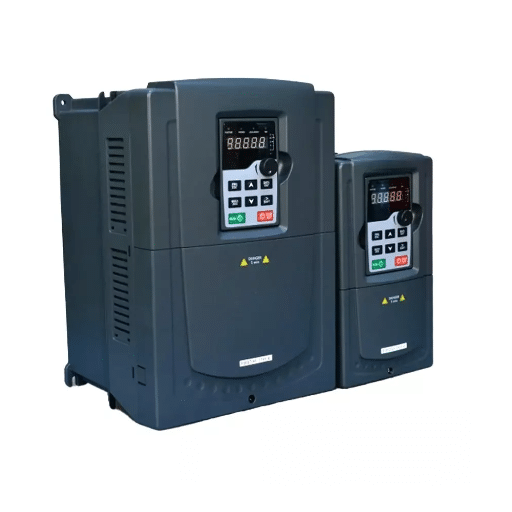
A single-phase variable frequency drive is supposed to get at least 220V or 240V single-phase AC input for an AC motor run, then must set the controlled AC output for the motor to accelerate. Now for this opportunity, it serves two distinct market performances. For some models, the output is single-phase AC for specific applications while an industrial system is most commonly set with three-phase AC output. The latter allows for conventional three-phase induction motors to run efficiently in places where only single-phase utility power is available.
All three components are put together inside a single case. The device begins by converting the incoming AC into DC voltage by employing a rectifier circuit. After that, the capacitors and inductors in the DC bus smooth out the voltage and filter out the ripple. The inverter inverts using pulse width modulation (PWM) to recreate the AC output enabling it to provide frequency and voltage at the most accurate values required for each speed for the motor.
If you are specifically looking to add speed control to an existing single-phase motor rather than replace it, see our dedicated guide on the VFD for single phase motor application, including which motor types are compatible and which are not.
Shandong Electric designs single phase VFDs for exactly these scenarios. Our drives accept 220V to 240V single-phase input and deliver stable three-phase output for motors ranging from small 0.75 kW units up to heavy industrial systems. If you are evaluating options, our low voltage VFD systems cover the full range of single-phase input requirements. For applications that already have three-phase power available, see our standard three-phase VFDs.
This where many novice buyers are confounded. They have bought a single-phase motor already, say, one with capacitor start from an old compressor or ventilation fan. They wonder whether they can just put a VFD on that existing motor for speed control and energy savings.
To simplify, no, the traditional single-phase motors operate on the basis of centrifugal switch and starting capacitor arrangement which produces the rotating magnetic field during start. When you vary the frequency via a VFD, the motor will never reach the consistent speed the centrifugal switch is waiting for to make its switch. Result? The switch opens and closes, tensing the capacitor, causing the motor to fail much more quickly, often within just a few hours.
The sustainable approach is to replace a single-phase motor with a three-phase motor and power it using a single-phase VFD to allow variable speed control with phase conversion. This feature will also lessen the utilization of a mechanical centrifugal switch and facilitate soft starting leading to increased bearing life.
In 2023, a pump system requiring an upgrade was housed in a water treatment plant in Arizona. Powered by 220V single-phase electricity, the maintenance crew attempted to keep the existing motor (single-phase) while adding a VFD for keeping the speed under control. The motor burned out within three days. Once the one-phase VFD was appropriately sized to the real load, everything worked excellent with the three-phase motor in place. The plant manager later agreed to having made the best maintenance decision they had that year.
Understanding the internal process helps you make better purchasing and installation decisions. A single phase to three phase VFD works through four distinct stages, each critical to safe and efficient motor operation.
The drive uses a diode bridge rectifier to convert the incoming single-phase AC into DC voltage. Because only two of the three input diodes in the bridge are active with single-phase power, the current per diode is significantly higher than with three-phase input. This is the primary technical reason that derating is necessary for single-phase input applications.
Capacitors on the DC bus absorb the rectified voltage and reduce ripple. A stable DC bus is critical because any voltage fluctuation will transfer directly to the motor output and cause torque pulsation or overheating. High-quality drives use larger capacitor banks to handle the increased ripple that comes with single-phase rectification.
Insulated Gate Bipolar Transistors (IGBTs) switch the DC voltage on and off at high frequency using PWM. By carefully controlling the switching pattern, the drive synthesizes three separate AC waveforms, each spaced 120 degrees apart. This creates a true three-phase supply that the motor recognizes and runs on smoothly.
The drive’s microprocessor continuously adjusts output voltage and frequency according to the selected control mode. V/F control maintains a constant voltage-to-frequency ratio, which is ideal for general-purpose fans and pumps. Vector control provides precise torque and speed regulation, making it the better choice for conveyors, machine tools, and other demanding loads.
For a deeper walkthrough of the complete conversion process with wiring diagrams and parameter settings, (see our single phase to 3 phase VFD guide. )Mitsubishi Electric also offers a clear technical overview of this phase-conversion process for remote industrial applications, which you can read here.

The most crucial step in sizing is selection. One careless error and the drive will trip on overcurrent, overheat, or find an early grave. There are no ifs and buts when dealing with this rule: Size the VFD about 2 times the motor’s full-load rating in HP or kW.
The rationale for this becomes obvious once you do the math. With a three-phase input, the current is split between the rectifier diodes, cooperation is shared with trying to make the best out of the not-so-good situation; with a single-phase input, on the other hand, only two diodes carry the full load. The current per diode, which is conducting, rises by a factor equivalent to the square root of 3 and is by the tune of 1.73-more or less. That’s why most manufacturers propose the derating factor; it’s primarily concerned with protecting the rectifier and ensuring long-term system reliability.
As a matter of fact, consider the case of an induction motor 3 HP (2.2 kW) 220V, where you could be persuaded in buying a 3 HP SFD as both power ratings match. The correct option for single-phase connection is to buy a 5 HP (4 kW) drive. This delineates the current margin required for the slip prevention of fault tripping (nuisance trips) as well as warranty claims from the respectives.
Voltage compatibility matters just as much as power rating. There are three common configurations to choose from:
Never attempt to run a 380V motor on a 220V output. The undervoltage will cause the motor to draw excessive current, overheat, and eventually burn out the windings.
We also strongly recommend installing a 5% line reactor on the input side. This simple addition reduces inrush current, protects the rectifier diodes, and improves the input power factor. KEB America provides excellent guidance on line reactor selection for single-phase VFD installations.
If you are unsure which voltage class or power rating fits your motor, our (how to size a VFD for motor guide) walks through FLA matching, load-type derating, and environmental factors in detail. For a direct comparison of specific drive models by budget and application, (see our best VFD for 3 phase motor control buyer’s guide. )You can also browse our full range of motor control. solutions to compare specifications.
For a dedicated step-by-step wiring walkthrough with terminal diagrams and a pre-power checklist, see our single phase VFD wiring installation guide.
Proper installation separates a reliable system from a troublesome one. Follow these guidelines for safe, stable, and long-lasting operation.
Connect the single-phase supply to the R and S terminals on the VFD input. Leave the T terminal unconnected. Do not jumper T to R or S unless the manufacturer specifically allows it in the installation manual, as this can create a phase imbalance fault.
Connect the motor leads to the U, V, and W output terminals. Ensure the motor is internally wired for the correct voltage, delta or wye, according to the motor nameplate. A mismatch here will cause immediate overcurrent or under-voltage problems.
Install the input line reactor between the power disconnect and the VFD input terminals. Size it for 5% impedance at the drive’s rated input current. The reactor should be mounted close to the drive but with adequate ventilation clearance.
Single-phase input VFDs often run at higher internal temperatures than their three-phase counterparts because of the increased input current. Maintain at least 100 mm clearance above and below the drive for airflow. If the environment contains dust, moisture, or corrosive vapors, use an enclosure with the appropriate IP rating for the conditions.
Use a dedicated ground wire connected directly to the VFD’s ground terminal. Keep motor cables separate from control and sensor cables to minimize electromagnetic interference. For drives operating near sensitive electronics, add an output reactor or sinusoidal filter.
Three-phase motors rely on their internal fan for cooling. At very low speeds, that fan moves too little air. Do not operate the motor at less than 20% of base speed for extended periods without adding a separate forced-ventilation fan to the motor.

Single phase VFDs bridge the gap between residential power infrastructure and industrial motor performance. They are especially valuable in locations where three-phase utility service is unavailable or would cost tens of thousands of dollars to install. Whether you need a VFD for 3 phase motor operation in a workshop or want to know how to run 3 phase motor on single phase power for an agricultural pump, these drives provide the answer.
For a deep dive into pump and fan specific sizing, PID tuning, and payback calculations, see our VFD for pumps and fans application guide.
Irrigation pumps, grain conveyors, and ventilation fans often operate in rural areas with only single-phase power. A properly sized VFD provides soft starting, which reduces water hammer in pump systems, and precise flow control, which cuts energy use during off-peak demand periods.
Rooftop units, chilled water pumps, and air handlers in smaller commercial buildings benefit significantly from variable speed control. The VFD matches fan or pump speed to actual thermal demand rather than running at full speed and throttling with dampers or valves. This alone can cut energy consumption by 20–50%.
Small lift stations, pressure booster pumps, and filtration systems use single-phase VFDs to maintain constant pressure while reducing mechanical wear. Soft starting also reduces stress on pipes and joints, lowering long-term maintenance costs.
Workshops and small manufacturing facilities use a single phase VFD to run three-phase lathes, milling machines, conveyor systems, and packaging equipment. The ability to vary speed improves surface finish on machined parts and allows a single motor to handle multiple product sizes on a conveyor line.
The business case for a single phase VFD extends far beyond simple phase conversion. A well-sized single phase VFD delivers measurable energy savings, equipment protection, and operational flexibility that directly impact the bottom line.
On variable-torque loads like fans and pumps, energy savings typically range from 20% to 50%. The physics is elegant: power required by a fan or pump drops with the cube of speed. Reducing motor speed by just 20% can cut energy consumption by nearly 50%. That is why HVAC and water systems see such rapid payback from VFD retrofits.
For a complete worksheet and step-by-step formulas to calculate payback and ROI for your specific application, use our VFD energy saving calculation guide with printable worksheets.
Government data supports these figures. According to the U.S. Department of Energy and NREL, retrofitting VFDs onto variable-load motor systems can reduce total industrial motor-system energy consumption by approximately 8% at the national level. ABB’s 2024–2025 screening campaign of over 10,500 industrial motor systems found that prioritized variable-load applications achieved average savings of 43%. Industry-wide research confirms that efficient motors and drives could cut global energy use by up to 10%.
Startup current is another major cost factor that VFDs eliminate. A 10 HP single-phase motor can pull 234 amps at startup, which is six to eight times its nominal running current. That inrush strains the electrical supply, trips breakers, and wears down motor windings. A VFD provides soft starting, ramping the motor smoothly from zero to operating speed without the current spike.
When compared to a rotary phase converter, a single-phase VFD often carries a similar upfront cost but pays for itself faster. For a complete engineering comparison of VFDs versus rotary and static phase converters, see our VFD vs phase converter guide. The VFD adds variable speed control, energy optimization, and built-in motor protection that a rotary converter cannot provide. Most small-shop and commercial installations see a complete payback period of 12 to 24 months through energy savings and reduced maintenance.
Sarah Okonkwo is another contractor who owns an HVAC business small in scale in Texas. In the summer of 2024, she had retrofitted a five-horsepower rooftop unit to a single-phase input VFD in a building. The building had single-phase power, not three-phase power. The client, during peak season, was coughing up $2,800 per month for cooling. The billing now states that the bill is still $2,800 for cooling during the peak season. Only this time, after the retrofit, there were substantial adjustments, which led to a reduction to $1,900 per month. This implies the equipment paid for itself during the first 14 months. The client plans on getting three more units’ retrofit with the same method.

For a dedicated fault-code reference and 10 common fixes you can complete in under 30 minutes, see our single phase VFD troubleshooting guide.
Even a correctly sized and installed single phase VFD can encounter operational problems. Here is how to diagnose and resolve the most common faults quickly.
First, verify that voltage is actually present between all three output terminal pairs: U-V, V-W, and U-W. If one pair reads zero or significantly lower than the others, the drive may have a failed output IGBT. Next, run the drive at no load up to 50 or 60 Hz and observe the display. If the motor still does not turn, check the motor bearings for seizure and measure the winding resistance with a multimeter.
This usually happens when the VFD is undersized or when additional loads, such as machine controls or contactor coils, are drawing current from the VFD output. A VFD should power only the motor. Wire any external controls, relays, or contactors to the VFD’s dedicated control terminals, not the motor output terminals.
Three-phase motors are not designed for extended low-speed operation without auxiliary cooling. If your application requires continuous low-speed running, add a separate constant-speed cooling fan to the motor. Also verify that the VFD parameter settings match the motor’s rated voltage, frequency, and current.
For single-phase pump applications, erratic current often indicates an incorrect control mode or pump-specific parameter setting. Switching from standard V/F control to a pump-specific V/F curve or sensorless vector control can stabilize the output current and improve system efficiency.
A single phase VFD is far more than a temporary fix for missing three-phase power. It is a complete motor control solution that delivers phase conversion, energy savings, soft starting, and equipment protection in one compact, cost-effective package.
The key takeaways are clear and actionable. Replace the old single-phase motor with a three-phase motor rather than attempting to control the single-phase motor directly. Size the VFD at approximately 2 times the motor’s nameplate power to account for single-phase input derating. Install a 5% line reactor on the input side to protect the rectifier and improve power quality. Expect 20–50% energy savings on variable-torque applications such as fans and pumps. And always maintain adequate ventilation and minimum speed limits to protect the motor.
Whether you are operating a machine shop, managing an irrigation system, or maintaining a commercial HVAC unit, the right single phase VFD lets you run three-phase equipment without expensive utility upgrades. You gain precise speed control, lower energy bills, and longer equipment life.
Ready to select the right drive for your application? Contact Shandong Electric today for expert engineering guidance, or explore our 3-phase VFD range to find the perfect match for your next project.