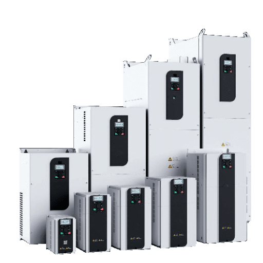
Ready to Get Your VFD Solution?
Whether you need a single drive or a complete system, we have the VFD products and engineering support to ensure your project's success.
So, what happens when your facility only has single-phase power and your equipment demands three-phase power? For many small workshops, rural factories, and light industrial facilities, this is not a hypothetical problem; rather, it is an unremitting headache that can slow down production, jack up costs, and generally prevent growth.
Running a three-phase motor in single-phase without a proper remedy leads to severe derating, inefficiency, and premature motor failure. A single-phase to a three-phase VFD provides an answer to these problems by converting its present single-phase input into a true three-phase output. This guide will delve into the precise working of the VFD in this conversion, how to correctly size and wire it, and the setting of parameters for long-term, reliable performance.
Marcus had confronted himself with the same dilemma when the young machinist opened his precision shop in Ohio in the spring. His building had 240 V single-phase service, and had the used CNC lathe he just bought it down to 460 V three-phase. Installing a primary 3-phase setup would cost him $18,000; $18,000 he’d rather save. Instead, Marcus installed a high-grade VFD to run on a single phase. In a single day, the machine ran to full torque and saved Marcus $18,000 in utility costs.
For a deeper dive on single-phase input configurations, (see our guide to single phase vfd guide)

A Variable Frequency Drive (VFD) is a three-step electronic process called the AC-DC-AC conversion that can convert single-phase input into the output of three phases; the description of this process helps understand what a true three-phase power source is.
Stage 1: Rectification. The VFD’s rectifier circuit takes the single-phase AC input and converts it to DC voltage. In a single-phase setup, this happens across two input terminals instead of three, which creates higher ripple on the DC bus.
Stage 2: DC Bus Smoothing. Capacitors and sometimes inductors on the DC bus filter out voltage ripple and store energy. This stable DC voltage becomes the “raw material” for the output stage.
Stage 3: Inversion. Through utilizing Pulse Width Modulation (PWM), the Insulated Gate Bipolar Transistor (IGBT) is made to switch the DC voltage on and off at a high frequency. By controlling the switching pattern in sequence via PWM, the VFD ultimately recreates three separate AC waveforms offset by 120 degrees.
The VFD does not simply split single-phase power into three uneven legs. It synthesizes three independent sinusoidal waveforms with precise 120-degree phase displacement. This gives you:
This is fundamentally different from static phase converters, which create an artificial third leg that often delivers unbalanced voltage and reduced motor performance.
Not every single-to-three-phase application is best served by a VFD. Choosing the right technology depends on your load type, need for speed control, and whether you are powering one machine or an entire shop.
| Feature | VFD | Rotary Phase Converter | Static Phase Converter |
|---|---|---|---|
| Output quality | True 3-phase, balanced | Good, near-balanced | Unbalanced, limited |
| Speed control | Full variable speed | Fixed speed only | Fixed speed only |
| Motor torque | Full rated (when sized) | Near full rated | 50-60% rated |
| Energy efficiency | 95-98% | 80-90% | 70-80% |
| Soft start | Built-in | No | No |
| Best for | Single motor, variable speed | Multiple machines, whole panel | Light loads, occasional use |
| Cost range | 200−200−2,500 | 1,000−1,000−5,000+ | 300−300−800 |
A single phase to 3 phase VFD is the optimal choice when:
A rotary phase converter may be better when:
The most important step in a successful installation includes sizing. Single-phase input causes high current draw and thermal stress on the VFD rectifier section. Undersizing accounts for most precocious failures.
On a three-phase supply, current divides across three input terminals. On single-phase, the same motor power must be delivered through only two terminals. This means:
The standard engineering rule for single-phase input is:
VFD rated current ≥ 1.5 × motor Full Load Amps (FLA)
In horsepower terms, this generally translates to oversizing the VFD by 50-100% compared to the motor rating.
Worked example:
Some manufacturers offer VFDs specifically designed for single-phase input. These units typically include:
Through utilizing Pulse Width Modulation (PWM), the Insulated Gate Bipolar Transistor (IGBT) is made to switch the DC voltage on and off at a high frequency. By controlling the switching pattern in sequence via PWM, the VFD ultimately recreates three separate AC waveforms offset by 120 degrees.
Need help confirming your motor parameters? Our guide on how to size a VFD for your motor explains how to match drive current to motor FLA and confirm variable torque duty.
Correct wiring ensures safety, performance, and longevity. Follow these steps carefully, and always consult a qualified electrician if you are not experienced with industrial electrical work.
Before applying power:
Parameter configuration is where theory becomes practice. Entering the correct motor data ensures the VFD delivers appropriate voltage, current, and frequency to the motor.
Program these parameters first, before running the motor:
| Parameter | Typical Code | What to Enter |
|---|---|---|
| Motor rated voltage | P0.02 or F0.02 | Motor nameplate voltage (e.g., 230V or 460V) |
| Motor rated frequency | P0.03 or F0.03 | Typically 50 Hz or 60 Hz |
| Motor rated current | P0.04 or F0.04 | Motor FLA from nameplate |
| Motor rated RPM | P0.05 or F0.05 | Nameplate base speed |
| Motor pole count | P0.06 or F0.06 | Usually 2, 4, or 6 poles |
Note: Parameter numbers vary by manufacturer. Always consult your VFD manual.
Set acceleration time long enough to prevent overcurrent trips but short enough for operational needs. A good starting point:
Soft starting reduces mechanical shock and extends motor and drivetrain life.
The first time installing a single phase-to-3 phase VFD used on a 3 HP pump in a small water treatment plant in Texas, the production crew refused to screw with any of the parameters and just pushed “go.” The water was running–that is, until the pump started overheating, tripping out on overload within 2 weeks. The motor’s nameplate data was correctly entered and the acceleration time was increased from 2 seconds to 8 seconds, bringing the system to normal operation for over a year.
A single phase to 3 phase VFD is not just a power conversion tool. It is also an energy optimization device that can deliver measurable operational savings.
For variable-torque loads such as pumps and fans, the affinity laws govern energy consumption:
Contrary to popular thought, reducing the fan speed by 20% cuts the power requirement at almost 50%. For instance, control of pump and fan applications can be done by variable frequency drive, which would account for substantial energy savings on the order of 20 to 50% when compared to the constant-speed operation.
Unlike direct-line motors, which draw reactive power from the grid and can operate at power factors of 0.70 as well as lower (and onwards), a variable frequency drive (VFD) maintains a power factor of 0.95 or higher on the input side. Drink diminutive utility-bearing responsibility charges and improve the total electrical efficiency.
For a 5 HP pump running 4,000 hours per year:
Typical payback periods for variable-load applications range from 1-3 years, according to the Electric Power Research Institute.
Even a properly sized and wired VFD can experience issues if environmental or parameter factors are overlooked. Here is a quick-reference framework for the most common field problems.
Causes:
Solutions:
Causes:
Solutions:
Causes:
Solutions:
Single phase to 3 phase VFDs are used across a wide range of industries and applications where three-phase utility power is unavailable or cost-prohibitive.
Water pumps and irrigation. Agricultural operators use VFDs to control pump speed based on flow demand, saving energy and reducing water waste.
HVAC fans and blowers. Variable airflow control improves comfort while cutting energy consumption by 30-50% in many installations.
Machine tools and CNC equipment. Small shops run precision equipment on single-phase supply using properly sized VFDs, avoiding expensive utility upgrades.
Compressors and conveyors. Soft starting reduces mechanical stress, while speed matching improves process control.
Small manufacturing and agricultural operations. From grain handling to packaging machinery, VFDs enable three-phase equipment deployment in rural and light industrial settings.
A sufficiently sized single-phase to 3-phase VFD is a highly efficient, adaptable, and cost-efficient solution for using three-phase motors on one-phase power. Unlike phase convertors, VFD provides true balanced three-phase power, motor protection integrated, dexterity of varying the speed and the big thrust derived toward energy-saving.
Here are the key takeaways:
Whether you are equipping a small workshop, upgrading rural infrastructure, or optimizing an existing process, the right VFD transforms a power limitation into a performance advantage.
If you are specifically looking to add speed control to an existing single-phase motor rather than replace it, see our dedicated guide on the VFD for single phase motor application, including which motor types are compatible and which are not.