Ready to Get Your VFD Solution?
Whether you need a single drive or a complete system, we have the VFD products and engineering support to ensure your project's success.

To wire a single-phase VFD correctly, attach one phase of your 220 V single-phased power to terminals R and S; the three-phase leads of the motor are connected to terminals U, V, and W, this should bond the drive chassis and motor frames to earth ground, making sure control wiring is isolated from the power conductors before first power-up. One wire placed in the wrong terminal, and the expensive VFD is now nothing but a paperweight.
The majority of online wiring guides show a three-phase input diagram; that is okay if you have three-phase power. For single-phase input VFD, however, they do not really tell you what to do with the T terminal. Single-phase VFD wiring has different current path, different terminal assignment, and differences in safety considerations as compared to the standard three-phase installation.
For single-phase VFD wiring, every terminal, wire, and connection process is navigable here, and you can learn how to size your wires, where each wire lands on the terminal block, how to otherwise properly ground and shield it, what parameters should subsequently be made ready. We even include a printable pre-power checklist for use in checking every wire, connection, and terminal before initial energization. Whether you are wiring a precision lathe in a shop or a pump at some remote facility, this guide will ensure you never have to repeat your work.
Key Takeaways
- Single-phase input power connects to terminals R and S only. Terminal T is left open or jumpered per the manufacturer manual.
- Motor output always connects to U, V, W in any order. Swap any two leads to reverse rotation.
- Use shielded cable for motor output with the shield terminated at the drive end only to prevent ground loops.
- Size input fuses or breakers at 1.5–2.0x the drive’s input current for semiconductor protection.
- Approximately 30% of VFD warranty returns are due to incorrect wiring or grounding, not product defects.
For a deeper dive on single-phase input configurations, see our guide to single phase vfd guide

Before you strip a single wire, study the terminal block layout on your drive. Every VFD has three distinct terminal zones: power input, power output, and control. Mixing these up is the fastest way to destroy a drive.
R, S, and T terminals are all line inputs. In a standard three-phase VFD, all three terminals are energized. In a single-phase input VFD, only R and S are energized. Terminal T is either left open or installed with an internal link, depending on the manufacturer design. Always refer to the drive manual for the certified single-phase input configuration. Do not assume T is the same as R and S.
With single-phase supply, the input current becomes almost exactly twice that for the same power motor on a three-phase supply. That is why the conductors feeding R and S must be sized according to the single-phase current at the higher level and not the three-phase current that is inscribed on the motor nameplate.
Terminals U, V, and W deliver variable-frequency, three-phase power to the motor, even though it runs on single-phase power. Inside is the VFD’s second stage. This actually generates three-phase output phases.
It does not matter if U is selected for either W or V during operation of the motor. Whichever way, the motor will run hard. If it does not rotate in the proper direction, debark power and consequently exchange two of the three among the motor leads. Never try to interchange the power lead with a motor connection lead.
The DC bus terminals (+ and -) carry high-voltage DC internally. Some drives expose these for external brake resistor connection. If your application needs fast deceleration of a high-inertia load, you will connect a braking resistor across the + and BR terminals (not + and -). Refer to your manual. Not all drives have a separate BR terminal.
The control terminal block is where you wire start/stop commands, speed references, and status outputs. These terminals carry low-voltage signals, typically 0–10V or 24V DC. They must be kept separate from power wiring. Running control wires in the same cable tray as power conductors invites EMI interference and erratic drive behavior.
Common control terminal functions include:
If you need to run a three-phase motor from a single-phase workshop supply, our guide to converting single-phase power to three-phase output explains the derating and wiring differences.

Gather the right tools before you open the enclosure. A well-prepared installation takes half the time of one done piecemeal.
Use copper conductors rated for 75°C minimum. For the input power (R, S), size the wire for the drive’s rated input current at single-phase voltage. For the motor output (U, V, W), size the wire for the motor’s Full Load Amps (FLA). NEC Article 430 recommends branch circuit conductors sized at 125% of motor FLA.
A quick-reference wire gauge table for common single-phase input VFDs:
| VFD Power | Input Current (1ph 220V) | Motor FLA (3ph 380V) | Input Wire (R, S) | Output Wire (U, V, W) |
|---|---|---|---|---|
| 0.75 kW | ~7 A | ~2.1 A | 14 AWG / 2.5 mm² | 16 AWG / 1.5 mm² |
| 1.5 kW | ~14 A | ~3.8 A | 12 AWG / 4 mm² | 14 AWG / 2.5 mm² |
| 2.2 kW | ~20 A | ~5.2 A | 10 AWG / 6 mm² | 14 AWG / 2.5 mm² |
| 4.0 kW | ~35 A | ~9.0 A | 8 AWG / 10 mm² | 12 AWG / 4 mm² |
| 5.5 kW | ~48 A | ~11.5 A | 6 AWG / 16 mm² | 10 AWG / 6 mm² |
| 7.5 kW | ~65 A | ~15.5 A | 4 AWG / 25 mm² | 10 AWG / 6 mm² |
Always verify against your specific drive manual and local electrical code. The table above is a starting reference, not a substitute for engineering calculation.
Size the input fuse or circuit breaker at 1.5 to 2.0 times the drive’s rated input current. Use semiconductor fuses (not standard motor fuses) for proper arc suppression if the drive suffers an internal fault. A disconnect switch rated for motor duty must be installed within sight of the motor per IEC 60204.
The cable from the VFD output (U, V, W) to the motor must be shielded to contain high-frequency switching noise. Use a three-conductor plus ground shielded cable. The shield is terminated at the drive end only, using the drive’s designated ground clamp or PE terminal. Do not connect the shield at the motor end. Grounding both ends creates a ground loop and defeats the purpose of the shield.
This is where most mistakes happen. Take your time. Double-check every terminal before you tighten a screw.
Run your single-phase supply conductors to terminals R and S. Tighten the terminal screws firmly. A loose connection creates heat, arcing, and eventually a fire hazard. Most VFD terminal blocks accept ferruled wire ends. If your drive specifies ferrules, use them. They prevent strand spreading and improve contact reliability.
On a single-phase input VFD, terminal T is not used for power. Some drives leave T as an open terminal. Others require an internal jumper between T and one of the other phases for the internal rectifier to balance. Read your manual. If it says to leave T open, leave it open. If it says to install a jumper, install the jumper. Guessing here is not an option.
When Ken, a maintenance technician at a textile mill in Indonesia, installed his first single-phase input VFD, he assumed T was just like R and S. He connected his 220V line to R, S, and T. The drive faulted on overvoltage within seconds and the input rectifier was damaged. The repair cost exceeded the price of the drive. The manual, which he had not opened, clearly stated: “For single-phase input, connect L1 to R and L2 to S. Leave T unconnected.”
Install a disconnect and overcurrent protection upstream of the drive. Size the protection at 1.5–2.0 times the drive’s input current rating. For example, a 2.2 kW single-phase input VFD with a 20 A input rating needs a 32–40 A breaker or fuse. This protects the supply conductors and the drive’s rectifier stage without nuisance tripping during startup.
The output side is simpler than the input, but shielding and grounding deserve careful attention.
Run your shielded motor cable from terminals U, V, W to the motor’s T-leads. Match the wire gauge to the motor FLA. Tighten terminals securely. There is no required phase sequence. The motor will run correctly with any permutation of U, V, W.
If the motor runs in the wrong direction, power down completely and wait for the DC bus capacitors to discharge (typically 5–10 minutes). Then swap any two of the three motor leads at the VFD output terminals. For example, exchange the wires on U and V. Power back on and verify direction.
Strip back the cable jacket at the drive end to expose the shield braid or drain wire. Connect the shield to the drive’s PE (protective earth) terminal or the designated shield clamp. Do not connect the shield to the motor frame at the far end. Single-ended shield termination routes EMI currents back to the drive chassis, where they belong, instead of circulating through your ground system.
Proper shielded cable grounding can reduce conducted EMI by 20–40 dB. For single-phase input VFDs, this matters even more than for three-phase drives because the input current waveform contains more harmonic content, which increases radiated noise.
Need help selecting the right shielded motor cable for your VFD installation? Explore our low voltage VFD solutions with application-specific cable recommendations.
Control wiring is low voltage, but it is also low tolerance for noise. A 0.5V spike on a 10V speed reference signal is a 5% speed error. Route control wires separately from power conductors.
The simplest start/stop circuit uses a normally-open pushbutton between the FWD terminal and COM. Pressing the button closes the circuit and starts the motor in forward direction. Releasing the button opens the circuit and stops the motor (coast to stop). For a latching start circuit, program the drive for two-wire control and wire a maintained contact or auxiliary relay.
To control speed with a manual potentiometer, connect the pot across VREF (10V), AI1 (wiper), and COM (0V). As you turn the pot, the voltage at AI1 varies from 0 to 10V DC, which the drive maps to 0–100% of maximum frequency. Use a shielded cable for the potentiometer leads, with the shield grounded at the drive end.
Need help confirming your motor parameters? Our guide on how to size a VFD for your motor explains how to match drive current to motor FLA and confirm variable torque duty.
Many drives support multi-speed presets selected by digital inputs. Wire additional switches or relay contacts from terminal S1, S2, S3 (or equivalent) to COM. Program the drive parameters to assign speed values to each input combination. This is useful for machines that need only a few fixed speeds, such as fans or mixers.
The relay output terminals (typically labeled TA, TB, TC) can signal a remote PLC or indicator lamp when the drive is running or when a fault occurs. These contacts are isolated and can switch low-voltage DC or AC loads up to their rated current. Do not use them to switch motor power directly.
Grounding is not optional. It is the foundation of safe VFD operation and reliable EMI performance.
Connect the drive’s PE terminal to the panel’s main ground bus with a dedicated green/yellow conductor sized to match the input power conductors. Do not daisy-chain grounds from one device to another. Each device needs its own direct path to the ground bus.
Run a separate ground conductor from the motor’s ground terminal back to the VFD’s PE terminal, not to a local building ground. This keeps the motor frame at the same potential as the drive chassis and prevents circulating currents. The motor ground conductor should be the same size as the motor power conductors.
Single-phase input VFDs draw pulsating DC current from the supply, which creates more harmonic content than balanced three-phase input. This increases both conducted and radiated emissions. Proper shielding, single-point shield termination, and segregated control wiring are essential for clean operation. If you experience erratic behavior, chattering contactors, or PLC faults near the drive, poor EMC practice is the most likely cause.
Not every application needs a brake resistor. But if you are decelerating a high-inertia load, such as a large flywheel or centrifugal fan, the motor acts as a generator during slowdown and pumps energy back into the drive’s DC bus. Without a place to dissipate that energy, the bus voltage rises and the drive faults.
Add a brake resistor when:
Most drives with braking capability have a + terminal (positive DC bus) and a BR or P/+ terminal for the resistor. Connect the resistor across these two terminals. The resistor gets hot during braking. Mount it outside the drive enclosure or in a well-ventilated area. Size the resistor wire for the duty cycle and peak current specified in the drive manual.

Do not power on until every item below is verified. This checklist takes two minutes and can save you from a destroyed drive.
Print this checklist and tape it inside the enclosure door. Use it every time.
Wiring is only half the job. The drive will not run correctly until you tell it what motor is connected.
Enter the following from the motor nameplate into the drive’s parameter menu:
These parameters tell the drive’s control algorithm what the motor expects. Incorrect motor parameters cause poor torque, overheating, or current imbalance.
Start conservative. Set acceleration to 5–10 seconds and deceleration to 5–10 seconds for a standard load. For high-inertia loads, extend deceleration or enable the brake resistor. Aggressive ramp times trip the drive on overcurrent or overvoltage.
For general-purpose applications, V/F control is sufficient and easy to set up. For applications requiring high torque at low speed, such as lathes or hoists, select sensorless vector control (SVC). Vector control requires an auto-tuning sequence. Run the auto-tune routine after all motor parameters are entered.
Before loading the machine, run a no-load test:
If everything checks out, increase the maximum frequency to your operating setpoint and load the machine.

Even experienced electricians make these errors. Learn from others so you do not repeat them.
Connecting input power to U, V, W
This is the most expensive mistake. The output stage (IGBT inverter) is not designed to accept line power. The rectifier is on the input side. Reversing input and output destroys the inverter instantly.
Forgetting to handle terminal T on single-phase input
On some drives, T must be jumpered internally for single-phase operation. On others, it must remain open. Guessing wrong causes unbalanced rectifier current and premature failure.
Undersized input protection
A breaker sized for the motor FLA will nuisance-trip on drive inrush current. Size for 1.5–2.0x the drive input current instead.
Motor ground not bonded back to VFD
Grounding the motor to a local building ground instead of the drive’s PE terminal creates a potential difference. Circulating ground currents cause bearing damage and EMI problems.
Shield grounded at both ends
Grounding the motor cable shield at both the drive and the motor creates a ground loop. The shield becomes an antenna instead of a shield. Noise increases instead of decreasing.
For a dedicated fault-code reference and 10 common fixes you can complete in under 30 minutes, see our single phase VFD troubleshooting guide.
While actual diagrams depend on your specific drive model, the general topology for single-phase VFD wiring is consistent across manufacturers.
L1 (220V) -----> R (VFD Input)
L2 (220V) -----> S (VFD Input)
 T (Open or jumpered per manual)
 U (VFD Output) -----> Motor T1
 V (VFD Output) -----> Motor T2
 W (VFD Output) -----> Motor T3
PE (Ground) ---> VFD Chassis -----> Motor FrameFWD -----> [NO Start Button] -----> COM
REV -----> [NO Reverse Button] -> COM
VREF ----> Potentiometer Terminal 1
AI1 -----> Potentiometer Wiper
COM -----> Potentiometer Terminal 2Always refer to your drive’s manual for exact terminal designations and jumper settings. The diagrams above are illustrative, not universal.
How do you wire a single phase VFD?
Connect your 220V single-phase input to terminals R and S. Leave T open or jumpered per the manual. Connect the motor to U, V, W. Bond the drive chassis and motor frame to a common ground. Run control wiring separately from power wiring. Set motor parameters before the first test run.
What is R S T on a VFD?
R, S, and T are the line input terminals. On three-phase input, all three carry power. On single-phase input, only R and S are used. T is either left open or internally jumpered depending on the drive design.
What is U V W on a VFD?
U, V, and W are the motor output terminals. They deliver variable-frequency three-phase power to the motor. The phase sequence does not matter. Swap any two leads to reverse rotation.
What size wire for VFD installation?
Size input wires (R, S) for the drive’s rated single-phase input current. Size output wires (U, V, W) for the motor’s Full Load Amps. NEC recommends 125% of motor FLA for branch circuit conductors. Refer to the wire gauge table in this guide for common ratings.
Do I need a line reactor for single phase VFD?
A line reactor is recommended when the supply transformer is more than 10 times the VFD kVA, when voltage is unstable, or when multiple drives share a bus. For a single small drive with stable supply, it is optional but beneficial for harmonic reduction.
How do you ground a VFD properly?
Bond the drive chassis PE terminal directly to the panel ground bus. Run a separate ground conductor from the motor frame back to the drive PE terminal. Terminate the motor cable shield at the drive end only. Do not daisy-chain grounds.
Single phase VFD wiring is not complicated, but it is specific. Respect the terminal assignments. Size your wires for single-phase input current, not motor FLA. Ground everything to a common point. Keep control wiring away from power conductors. Use the pre-power checklist before every first start.
Get the wiring right, and your drive will start cleanly, run quietly, and last for years. Get it wrong, and you join the 30% of warranty returns that were never a product defect.
At Shandong Electric, we supply more than variable frequency drives. We provide wiring guidance, parameter setup support, and commissioning assistance to make sure your installation succeeds from day one. If you are planning a single-phase VFD installation and need application-specific advice, contact our engineering team. We will help you wire it right, the first time.
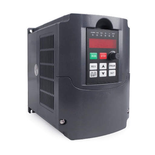
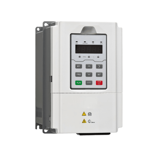
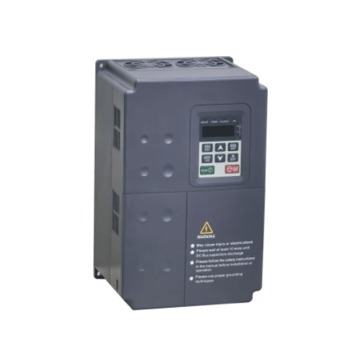
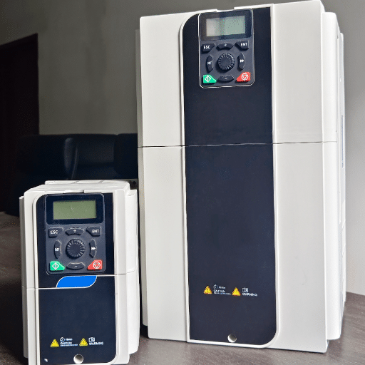
Need a VFD with clear terminal markings and included wiring instructions? Browse our single-phase input VFDs designed for workshop and light industrial applications.