Ready to Get Your VFD Solution?
Whether you need a single drive or a complete system, we have the VFD products and engineering support to ensure your project's success.

Last updated:
VFD control wiring links switches, sensors or a programmable logic controller (PLC) to the drive. It carries run commands, speed signals and status signals. Start with the exact drive manual. Match each signal to its supply, return path and assigned input function.
A motor can run from the keypad while the terminal controls do nothing. That doesn’t prove the VFD control wiring is wrong. The run source may still be the keypad.
The speed reference may come from another source. This guide separates those paths so you can decide what to check before moving a wire.
Key takeaways
A variable frequency drive (VFD) changes its motor output to control speed. For the background, see how variable frequency drives work. Here, focus on the control signals that tell it when to run and which speed to use.
Identify the supply input, motor output, protective earth and control block on the actual unit. Labels such as L1/L2/L3 and U/V/W are common. Check their meaning and allowed supply in the manual. Never connect mains power to motor-output or control terminals.
DC-bus, reactor and braking terminals belong to separate circuits. They aren’t spare signal terminals or automatic requirements for a basic control circuit. The Yaskawa J1000 connection extract, printed pages 39-43, distinguishes these connections and warns against applying supply power to option terminals.
VFD control wiring starts with this boundary. Mark each terminal group on your drawing before choosing cable cores or assigning PLC outputs. If the equipment uses a permitted single-phase input, confirm that model’s input arrangement separately; don’t infer it from a three-phase example.

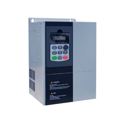
The exterior photo provides general drive context. It doesn’t identify the terminal board or show internal component connections.
Record the full model and hardware series. Note the fitted options and manual revision. Add firmware details if they affect input settings. A drawing for another unit in the same family may show a different control block.
Before touching wires, qualified personnel must isolate all relevant sources. Follow the specified discharge wait, then verify that hazardous voltage is absent. Include external control supplies.
A dark display or stopped shaft doesn’t establish isolation. Follow the equipment manual and site procedure; this article isn’t a substitute for them.
For a VFD control wiring review, keep the diagram beside a list of active settings. Use our VFD parameter settings guide to organize command-source and reference-source checks before the first run.
Illustrative scenario: A conveyor runs from the keypad but ignores a remote switch. First compare the selected run source with the terminal-input monitor. If the input changes but the run source remains local, changing cable cores won’t address that setting. If the input never changes, inspect the isolated circuit against the drawing before planning controlled diagnostics.
A terminal name is a clue, not a complete instruction. In VFD control wiring, identify the function, allowed signal and return path together. The same input can serve different jobs after you change a macro or setting.
Use this function map to read a manufacturer drawing. It is a concept table, not a construction schematic.
| Terminal function | What it does | What to confirm |
|---|---|---|
| Digital input | Receives a discrete command such as run or reset | Assigned function, polarity and input logic |
| Analog input | Receives a changing speed or process reference | Voltage/current mode, range and return |
| Control supply | Powers the permitted control circuit | Voltage, current capacity and external-supply rules |
| Digital common | Completes the digital input circuit | Which input group and supply it belongs to |
| Analog common | Provides the specified signal return | Isolation and bonding instructions |
| Relay or transistor output | Reports an assigned drive state | Output type, load limits and status assignment |
| PE or shield connection | Serves the documented protective or EMC role | Correct termination and bonding method |
See the electrical installation and application-macro sections of the ABB ACS355 manual. They show how input duties change with the selected macro. A factory diagram doesn’t prove the current assignment on an installed drive.
An analog input carries a value, such as a voltage or current reference. A digital input represents a command state. Don’t connect an analog source to a digital input just because both appear in the control block. Record both jobs in your VFD control wiring schedule.
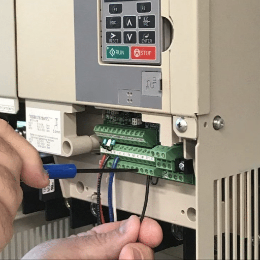
This terminal-work photograph is illustrative. It doesn’t establish the isolation state or authorize copying the pictured connections.
PNP outputs source current; NPN outputs sink current. The drive input circuit must match the PLC output and the selected logic. Source and sink can describe different sides of that circuit. Trace the full path in both manuals.
For each VFD control wiring input, trace where current starts and returns. Follow its path through the PLC output and drive input. Check the selector or jumper position against that path. Don’t change it while energized or assume an output is a dry contact.
Choose the control supply from the approved drawing. It may be internal or external. Check the manufacturer’s permitted connections before joining commons or supplies.
Don’t parallel supply outputs by guesswork. If the permitted arrangement is unclear, stop that connection and obtain the matching drawing.
Our Siemens VFD overview provides product-family background. Obtain the exact model’s control drawing before using any terminal numbers; an overview doesn’t establish a pinout.
These names describe command behavior. They don’t count every conductor in the cabinet. Choosing between them changes both the VFD control wiring and the way the drive interprets its inputs.
For two-wire VFD control wiring, a maintained contact or PLC state holds the run request. Removing that state requests the configured stop. Direction can use another input or a different assigned arrangement, depending on the drive.
Don’t treat an open run contact as electrical isolation. Stop behavior follows the selected mode, such as ramp or coast. The PowerFlex 520-series manual separates stop settings, input assignments and source selection; check the correct 523/525 hardware section.
For three-wire VFD control wiring, a momentary start signal requests running. A separate stop circuit cancels that state. The cited J1000 example uses a normally open start and normally closed stop. Those contact descriptions apply to that documented example, not every input configuration.
The drive must be set for the intended sequence before the circuit is put into service. ABB’s three-wire macro illustrates changed input duties. Yaskawa’s J1000 extract, printed page 41, warns that mismatched sequence settings and power-up acceptance can cause unexpected movement.
| Control concept | Run request | Stop request | Configuration decision |
|---|---|---|---|
| Maintained control | Held command state | Remove the request | Input assignment and restart behavior |
| Momentary control | Start pulse accepted by the sequence | Separate normal-stop input | Sequence mode, stop assignment and direction |
This comparison is not a wiring diagram. For VFD control wiring, copy neither contact numbers nor terminal names across brands. Select the manufacturer’s complete circuit, including its supply and common connections.
For a model-specific walkthrough, Schneider embeds the following ATV320 two-wire setup video in its linked FAQ. Use it with the matching manuals; it is not a generic terminal drawing.
A run signal can stay on after power fails or a fault resets. Check how the drive is set to handle it. Schneider’s ATV320 two-wire guidance distinguishes transition and level behavior; that decision must fit the machine’s restart policy.
Write down what should happen when power returns or a fault clears. Include a change from local to remote control. Check what happens if direction signals conflict.
Then verify the corresponding manual settings. Don’t test these states until motion risk is controlled through the approved commissioning procedure.
Returning to the conveyor example, the useful result is a matched switch type, input function and command source. There is no basis to claim a successful repair until the circuit and behavior have been checked. Keep that distinction in the VFD control wiring handover.
An analog reference specifies a requested value; it doesn’t itself grant permission to run. For VFD control wiring, treat the run path and reference path as separate circuits even when one PLC controls both.
For VFD control wiring with a potentiometer, identify the specified reference supply, analog return and wiper connection. The wiper feeds the selected voltage input. Choose resistance and power ratings from the exact manual; a reference-supply terminal isn’t a general-purpose cabinet supply.
Schneider’s ATV320 terminal-control FAQ gives a model-specific example: a voltage reference uses AI1 and COM, while a potentiometer uses +10, AI1 and COM. It also lists TCC and FR1 settings for that setup. These apply to the ATV320 example. Don’t copy them to an unknown drive.
A PLC analog output provides the signal. A loop-powered transmitter needs a source to power its loop. They cannot be treated as the same circuit just because both use a current signal.
The IH ACN installation chapter, printed pages 2-26 to 2-28, shows separate drawings for a speed pot, PLC voltage output, PLC current output and loop-powered transmitter. Use those distinctions to select the right kind of drawing for your hardware.
| Reference source | Connection concept | Decision before wiring |
|---|---|---|
| Passive potentiometer | Reference supply, wiper and analog return | Permitted pot rating and voltage input |
| Active PLC voltage output | Signal and designated return | Input range and output compatibility |
| Active PLC current output | Current signal and specified return | Active/passive pairing and allowed load |
| Loop-powered transmitter | Supply and signal path form a loop | Who powers the loop and the complete return path |
The table helps classify VFD control wiring; it provides no terminal pinout. Never add another supply to a current loop without confirming the complete circuit.
For analog VFD control wiring, check any physical voltage/current selector and the matching parameter. Then confirm that the drive takes its reference from that input. Finally, check how the input range maps to the allowed speed range. Correct VFD control wiring cannot fix a wrong reference-source setting.
For a scoped example, open the PowerFlex 523 Series A drawing on printed page 38 of publication 520-UM001O. It shows a 0-10 V input at terminal 13 and analog common at 14. Terminal 15 takes a 4-20 mA input.
Verify series and manual revision before applying those numbers. They aren’t interchangeable input terminals.
Illustrative scenario: A pump receives a run request but its speed doesn’t follow the PLC reference. Compare the drive’s input display with the selected voltage/current mode and reference source. If those disagree, resolve the configuration against both manuals before assuming a motor fault.
Record the expected signal type, selected input and displayed reference. Leave the result open until each check has been completed.
Include loss-of-reference behavior in the VFD control wiring record. Decide how the process should respond to a broken loop. Check that the drive supports the chosen response. Don’t assume it is a safe stop.
VFD control wiring also carries information out of the drive. A run lamp, PLC status input and analog monitor need the right output type and function assignment.
For VFD control wiring to a status output, first check its type. A relay may provide dry contacts. A transistor output needs a compatible supply and load circuit.
Check the output rating and allowed load. Use the exact manual to identify the contacts. Don’t connect a contactor coil solely because a terminal is labelled output.
Also check what the output reports. A relay assigned to fault doesn’t prove that the motor is running. An analog output assigned to frequency isn’t a safety indication.
Write the output function beside the wire number. Check that the PLC logic and drawing agree.
Route VFD control wiring according to the drive’s EMC instructions. Keep signals apart from power and motor circuits as required. The PowerFlex manual includes control-I/O wiring notes; ABB also specifies control-cable and shield practices. Use the instructions that match the installation.
Don’t assume analog common, digital common, shield and protective earth are interchangeable. A return conductor completes a signal circuit. A shield and PE serve different documented roles. A bond added by guesswork can change the circuit.
For VFD control wiring cable decisions, use our EMC and shielding guide alongside the drive manual. Refer to VFD cable sizing for the separate conductor-sizing topic; terminal acceptance size alone isn’t an ampacity calculation.

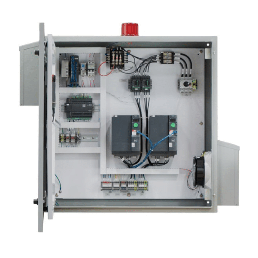
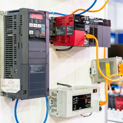
The panel photograph gives general motor-control context. It doesn’t demonstrate an approved safety circuit.
| Function | Purpose | Limit |
|---|---|---|
| Normal stop | Requests the configured operating stop | Doesn’t establish isolation or a validated safety function |
| Safe torque off (STO) | Prevents torque generation through the documented safety function | Doesn’t disconnect all hazardous voltage |
| Electrical isolation | Separates relevant energy sources for work | Requires the prescribed isolation and verification procedure |
The ACS355 manual’s STO appendix states that STO doesn’t disconnect main and auxiliary circuit voltage. It requires validation of the safety function. Don’t bypass safety inputs to make an ordinary run command work. VFD control wiring checks cannot replace the machine’s safety assessment or acceptance test.
Check what the drive sees before blaming the motor. Divide VFD control wiring checks into isolated inspection and controlled energized observation; don’t move between them without the approved procedure.
These VFD control wiring checks complement the manufacturer’s installation checklist. They don’t establish that the entire machine is ready to start.
Qualified personnel can use the drive’s input and reference displays in a controlled test. Follow the manual’s test method. Compare the switch or PLC request with the input state, then compare that state with its assigned function. Check the reference display separately from the run request.
If a test needs electrical measurements, qualified personnel must use the maker’s method and suitable tools. Don’t reconnect leads or change selectors on an energized unit. Don’t bypass permissives or safety functions to obtain a test run.
| Observed symptom | Next check | What it doesn’t prove |
|---|---|---|
| Keypad works, remote run doesn’t | Command source, input state and assignment | That the motor or drive needs replacement |
| Input state never changes | PLC output type, permitted supply and return path | That a software change alone will help |
| Run request is accepted, reference stays low | Reference source, input mode and scaling | That more run wiring is needed |
| Speed reference fluctuates | Compare source command, input display and cable route | That the signal cable is the confirmed cause |
| Status disagrees with PLC indication | Output assignment, output type and PLC input circuit | That the status signal is safety-rated |
Illustrative scenario: A speed reference fluctuates when nearby equipment operates. Record whether the PLC command changes at the same time as the drive’s reference display. Inspect the isolated signal route and shield arrangement against the manual.
If the changes occur together, use that clue to choose the next test. It doesn’t prove that noise is the cause. Don’t add an unapproved earth bond.
Save the observed VFD control wiring states and fault history before changing settings. For broader acceptance work, use the VFD testing checklist. This article covers control I/O decisions, not a complete commissioning test.
No. A 0-10 V or 4-20 mA reference is an analog signal. A digital input receives an assigned discrete command. Select the input type and return from the manual, rather than treating every control terminal alike.
Don’t assume so. The input duties and sequence must match the new VFD control wiring circuit. ABB’s macro examples and Yaskawa’s sequence warning show why a pushbutton change requires a settings review before service.
Not automatically. COM identifies a common in a particular circuit. Follow the drive’s grounding and bonding instructions instead of adding a link to PE by assumption.
The run source, speed-reference source, input assignment or current path may differ from what you expect. Trace each path separately. A working keypad test doesn’t validate the VFD control wiring.
Hand over the checked drawing with model details and wire identities. Include the selected input functions and restart policy.
For supply installation, see single-phase VFD wiring where relevant.
For further background, see the system-design PDF, reliable-system white paper and V2-series manual as supplemental reading. Use the correct manufacturer drawing for construction.
Good VFD control wiring combines a compatible circuit, matching settings and recorded checks. For a drive application inquiry, contact our team with the drive model, supply, motor nameplate and intended control method. Include the manual diagram and identify which input or signal you need to discuss.