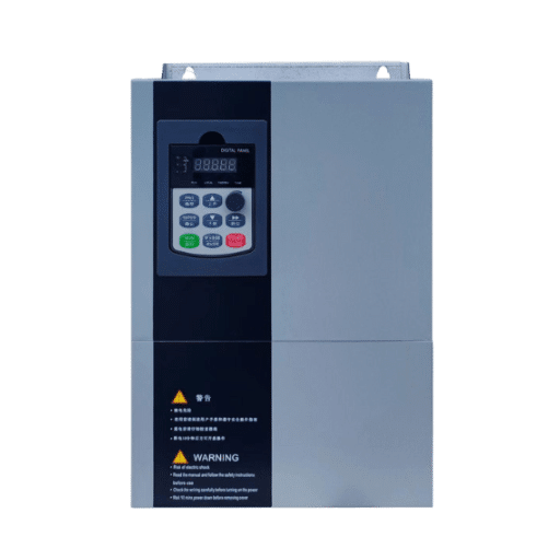
Ready to Get Your VFD Solution?
Whether you need a single drive or a complete system, we have the VFD products and engineering support to ensure your project's success.


A frequency inverter controls a motor by converting fixed-frequency grid power into variable-frequency, variable-voltage output, so the motor’s speed follows the frequency you command. In practice, motor control using a frequency inverter comes down to five decisions: wiring, nameplate parameters, command source, speed reference, and ramp settings. Get those five right and the motor does exactly what you tell it.
Here is what getting them wrong looks like. In March, a technician named Tomas commissioned a new 11 kW fan drive at a food processing plant in Gdansk. He wired everything correctly, powered up, pressed run, and the drive tripped on overcurrent in under two seconds. Every time. The cause took ten minutes to fix: he had never entered the motor’s nameplate data, so the drive was protecting a phantom motor with factory-default values meant for a much smaller unit. Five parameter entries later, the fan has run without a single trip.
If you are about to commission your first inverter, or your fifth, this guide walks the complete workflow in the order you actually perform it on site: wiring, nameplate parameters, command source, speed reference, ramps, and first run. At the end you will find the five beginner mistakes that account for most failed startups. This is the same sequence our support engineers walk Shandong Electric customers through on commissioning calls.
Key Takeaways
- A frequency inverter controls motor speed by varying output frequency; voltage scales with it to keep motor flux constant.
- Motor control using a frequency inverter is five sequential decisions: wiring, nameplate parameters, command source, speed reference, and ramp settings.
- The command source (who starts and stops the motor) and the speed reference (how fast it runs) are two separate decisions. Confusing them causes most setup failures.
- Skipping nameplate entry is the number one cause of instant overcurrent trips on first run.
- High-inertia loads need accel ramps of 30 to 60 seconds or more, far beyond the 5 to 20 second factory defaults.
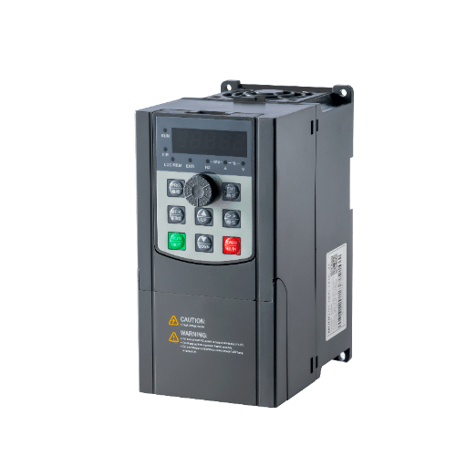
A frequency inverter controls a motor by adjusting the frequency of the power supplied to it. An AC induction motor’s speed is directly proportional to supply frequency, so raising the frequency speeds the motor up and lowering it slows it down. The inverter scales voltage along with frequency to keep the motor’s magnetic field stable across the whole speed range.
That is the entire principle. For the physics behind it, including the N = 120 x f/p relationship and slip, see our guide on the physics of frequency and motor speed.
Inside the unit, a rectifier converts incoming AC to DC, a capacitor bank smooths it, and an inverter stage rebuilds AC at the commanded frequency.
One terminology note before the workflow: frequency inverter, variable frequency drive (VFD), and AC drive are the same device. “Frequency inverter” dominates in European and international markets, so that is the term this guide uses.
The power connections have two sides, and they are not interchangeable. The input terminals (marked L1, L2, L3) take the grid supply. The output terminals (marked U, V, W) feed the motor. Wiring the motor to the input side applies full grid voltage through paths never designed for it and can destroy the drive instantly.
On the output side, phase order sets rotation direction. If the motor runs backwards, swap any two of the U, V, and W leads, or simply use the drive’s reverse command. Never try to change direction by rewiring the input side; input phase order is irrelevant to output rotation.
Before the first run, enter five values from the motor’s nameplate: rated voltage, rated current, rated frequency, rated speed (RPM), and rated power. These numbers tell the drive what motor it is actually protecting and controlling.
Skip them, and two things go wrong. The drive’s thermal protection model guards the wrong motor, which is exactly what tripped Tomas’s fan. And if you later switch to vector control, the drive’s motor model is built from these values, so poor nameplate data means poor torque performance.
Most drives also offer auto-tuning, which measures the motor’s resistance and inductance automatically. Run it after entering the nameplate data. Our guide to running motor auto-tuning covers the procedure.
Commissioning a drive soon? Our engineers verify nameplate entry, tuning, and parameter setup on every project we support.
The command source decides who tells the drive to run, stop, and reverse. There are three options, and each suits a different installation:
Here is the insight that untangles most beginner confusion: the command source and the speed reference are separate decisions. The command source controls whether the motor runs. The speed reference, covered next, controls how fast. You can start from a fieldbus while taking speed from a potentiometer, or start from the keypad while a PLC’s analog output sets speed. Mixing these two concepts up is the root of most “the drive ignores my settings” support calls.

The speed reference tells the drive what frequency to produce. This table compares the six common methods:
| Method | Signal | Best For | Example |
|---|---|---|---|
| Keypad up/down | Digital, internal | Manual speed setting on standalone machines | Bench grinder, test stand |
| Potentiometer | 0-10 V analog | Simple operator speed dial | Drill press, small mixer |
| 0-10 V analog input | Voltage from PLC/controller | Automated control over short cable runs | Conveyor speed from PLC |
| 4-20 mA analog input | Current loop from PLC/transmitter | Long runs, noisy environments, process control | Fan speed from BMS |
| Fieldbus (Modbus etc.) | Digital network | Multi-drive systems, full diagnostics | Production line coordination |
| Multi-speed presets | Digital inputs select fixed speeds | Machines with fixed operating steps | Mixer with slow/fast/clean cycles |
One comparison worth understanding: 4-20 mA versus 0-10 V. A current loop resists electrical noise over long cable runs, and its “live zero” means 4 mA, not 0 mA, represents minimum speed. If the loop breaks, the signal drops to 0 mA and the drive can detect the fault immediately. A 0-10 V signal cannot distinguish “commanded zero speed” from “broken wire.”
That distinction saved a packaging line in Rotterdam last year. Their PLC sent a 4-20 mA reference to the main conveyor drive. When a cable was damaged during nearby work, the drive flagged signal loss and stopped the line safely. On a 0-10 V reference, the same break would have silently commanded zero speed, jamming product against a stopped belt with the line logic blind to why.
Two parameter groups finish the basic setup.
Minimum and maximum frequency act as guardrails. Set the minimum above zero for loads that should never crawl (some pumps lose lubrication below a threshold) and cap the maximum where the process or motor demands it, typically 50 or 60 Hz.
Acceleration and deceleration times control how quickly the drive ramps the motor toward a new speed. Factory defaults are usually 5 to 20 seconds, sized for light loads. High-inertia loads need much more: a large fan, centrifuge, or lathe chuck may need 30 to 60 seconds or longer. Set the accel ramp too short and the drive trips on overcurrent, typically at 150% of rated current. Set decel too short and regenerative energy from the spinning load pushes the DC bus into an overvoltage trip, around 750 to 800 V on 400 V-class drives.
A machine shop in Wroclaw hit exactly this wall. Their lathe, with a heavy four-jaw chuck, tripped on every start with the 5-second default ramp. Extending acceleration to 25 seconds eliminated the trips permanently, and no hardware change was needed.
If your application needs strong low-speed torque or tight speed holding, the control mode (V/f versus vector versus DTC) matters as much as the ramps. That selection has its own framework; see our guide to choosing between V/f, vector, and DTC control modes.
Run this sequence before putting the motor into service:
Thirty minutes with this checklist prevents the large majority of first-run failures.

1. Motor wired to the input terminals. Instant drive destruction risk. L1/L2/L3 is supply; U/V/W is motor. No exceptions.
2. Skipped nameplate entry. The drive protects a phantom motor and trips on overcurrent, exactly like Tomas’s fan. Five parameters, ten minutes, problem gone.
3. Factory-default ramps on a high-inertia load. A 5-second accel time on a flywheel load is a guaranteed overcurrent trip. Match the ramp to the inertia.
4. Wrong reference source selected. The potentiometer does nothing because the drive is listening to the fieldbus. Check which source is active before blaming the hardware.
5. Direction surprise. The motor runs backwards on first start, driving a pump against a closed valve or a screw conveyor in reverse. Verify rotation at low speed, uncoupled if possible, and swap two output leads if needed.
Yes. Frequency inverter, variable frequency drive (VFD), AC drive, and variable speed drive all describe the same device. The term “frequency inverter” is dominant in Europe and international markets, while “VFD” is more common in North America.
Use the drive’s reverse command from the keypad, a control terminal, or the fieldbus. Alternatively, swap any two of the three motor leads on the U, V, W output terminals. Never rewire the input side; input phase order does not affect output rotation.
Yes. Connect a potentiometer to the drive’s analog input (typically 0-10 V) and select that input as the speed reference source. The dial then sweeps the motor between your minimum and maximum frequency settings.
The three most common causes are missing nameplate parameters, an acceleration time too short for the load’s inertia, or a wiring fault on the output side. Check nameplate entry first, extend the accel ramp second, and inspect the U/V/W connections third.
Motor control using a frequency inverter is not complicated once you see it as a sequence. Wire the motor to U/V/W. Enter the nameplate data. Choose who commands the motor. Choose what sets its speed. Set the limits and ramps that match your load. Then run the checklist.
Do those five things in order, and a first commissioning takes about 30 minutes instead of a day of tripped drives and head-scratching. The theory layers, control modes, communication depth, and system design all have their place, and the linked guides cover them. But the workflow above is what gets a motor turning.
If you would like that first startup guided by people who do it every week, Shandong Electric supplies frequency inverters across our complete drive range with commissioning support included. Contact our engineering team → with your motor nameplate data and application, and we will walk the checklist with you.