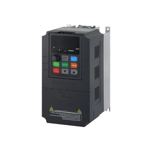
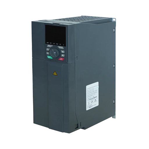
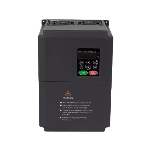
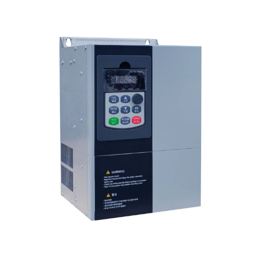
Ready to Get Your VFD Solution?
Whether you need a single drive or a complete system, we have the VFD products and engineering support to ensure your project's success.

VFD position control uses encoder feedback and a position loop in the drive or PLC. Compare the methods, accuracy limits, sizing, and commissioning steps.
A VFD can control position when it has encoder feedback and a position loop, either inside the drive or in a PLC. It typically holds 0.5 to 2 mm, or about 1.5 degrees, not the 0.01 mm a servo can reach.
This guide covers VFD position control on conveyors, indexing tables, cranes, machine tools, packaging lines, and similar industrial axes. It is not about HR position control, tractor draft control, or servo-only motion. Send the axis data to our engineers before you specify the drive.
Key Takeaways
- A VFD positions by counting feedback and correcting error. Without an encoder, it controls speed and position drifts.
- A PLC loop is cheaper at high axis counts; a drive loop is faster per axis. Encoderless positioning trades accuracy for cost.
- Gearing, backlash, decel repeatability, and latency matter more than encoder resolution. A 25:1 to 40:1 gearbox is the cheapest upgrade.
- A 1024 PPR encoder on a 40:1 gearbox can repeat an index to about plus or minus 1/16 inch. A servo reaches 0.01 mm.
- Position control needs closed-loop vector, a home reference, a brake sequence, and a following-error limit. A standard V/Hz drive will not hold at zero speed.
Position control is an outer loop. It compares a commanded position with a measured position and changes the motor command to close the gap. The drive still runs a speed loop and a torque loop underneath, but the position loop decides where the axis should be.
A speed loop holds rpm and lets position drift with load. A position loop holds position and accepts a speed change to do it. A conveyor run by speed control alone loses its stop point after a few cycles. If you need the arithmetic of speed regulation, see our guide to what speed accuracy actually means.
A torque-controlled VFD holds a commanded torque. It is useful for winding and tension, but it has no idea where the load is. A position loop needs a feedback device and a reference.
ABB’s position controller is a P-type controller. It calculates a velocity reference from position error and adds feedforward. The drive checks the error against a following-error limit and sets an in-position bit inside a position window. The details are in ABB’s position control program firmware manual.
Position control sits on top of closed-loop vector or DTC, not on top of open-loop V/Hz. For a refresher on V/F, sensorless vector, and closed-loop vector, see our guide to VFD control modes.
Every position axis needs feedback, a reference, a motion profile, and a hold. Feedback is an encoder, resolver, or absolute sensor. The reference is a home position or absolute value. The profile sets acceleration, deceleration, and a settle window. The hold is a brake or a zero-speed torque hold. Remove any one and the axis becomes a position-stop, not a closed loop.
An induction motor has no magnets. The rotor current is induced by the stator field, so the drive estimates rotor position instead of measuring it. Open-loop V/Hz can hold a speed, but not a position. Sensorless vector improves low-speed torque, but it still estimates position. Closed-loop vector with an encoder is the minimum for position control.
Daniel, a maintenance engineer at a carton plant, learned this on an index conveyor. The plant replaced a clutch-brake with a standard VFD in sensorless vector mode. The stop point drifted with product weight and belt temperature, and the line missed its print registration window. Adding a 1024 PPR encoder, selecting closed-loop vector, and homing on the index pulse fixed it.
| Architecture | Feedback | Where the loop runs | Best for | Main limit |
|---|---|---|---|---|
| PLC position loop | Encoder to PLC high-speed counter | PLC scan | High axis counts, slow moves, existing PLC hardware | Scan and network latency; tuning is custom code |
| Drive position loop | Encoder to drive | Drive, 500 microseconds on ABB ACS880 | Fast single axes, indexing, homing, synchronization | Drive cost per axis; product-specific setup |
| Encoderless open loop | Motor model estimate | Drive | Loose repeatability, cost-sensitive axes | No direct position measurement; error is not bounded by an encoder |
In a PLC loop, the encoder wires to a high-speed counter on the PLC, and the PLC sends a speed reference to the drive. A two-speed comparator runs fast until a preset position, then slow until the target. It is easy to build and produces abrupt speed changes and poor accuracy. A ramped speed reference scales speed to position error and works better.
One integrator’s field guide puts the in-position tolerance at 1 to 5 encoder counts. A PLC ramped-speed loop suits moves longer than 250 ms and tolerances of about 0.01 inch or looser, not 50 to 250 ms pick-and-place moves.
The economics favor the PLC at high axis counts. Marta, an OEM design engineer, specified a 57-axis palletizing line with a positioning drive on every axis. She kept a PLC ramped-speed loop on the slow axes and used drive-based positioning only on the two high-cycle axes. The line met its tolerance and the panel cost came down.
In a drive loop, the encoder wires to the drive, and the drive runs the position loop internally. The PLC sends a target position, a go signal, a speed, and acceleration and deceleration times over a fieldbus or digital inputs.
This architecture gives a VFD its best positioning performance. ABB’s position control flyer publishes a 500-microsecond position loop, a 500-microsecond speed loop, and a 125-microsecond torque loop. It supports homing, absolute and relative positioning, profiled positioning, position synchronizing, and fast position latching. The flyer lists HTL, TTL, sin/cos, EnDat, Hiperface, SSI, and resolver feedback. The trade-off is cost per axis and product-specific setup.
Some drives offer encoderless, open-loop positioning. ABB’s ACS880 position control page says it cuts component and cabling costs by estimating position from the motor model and the commanded motion. Treat it as a cost-reduction option, not a servo substitute. No source reviewed here publishes an accuracy figure for it, and the error is not bounded by an encoder. Use it only where the load is predictable and the tolerance is loose.
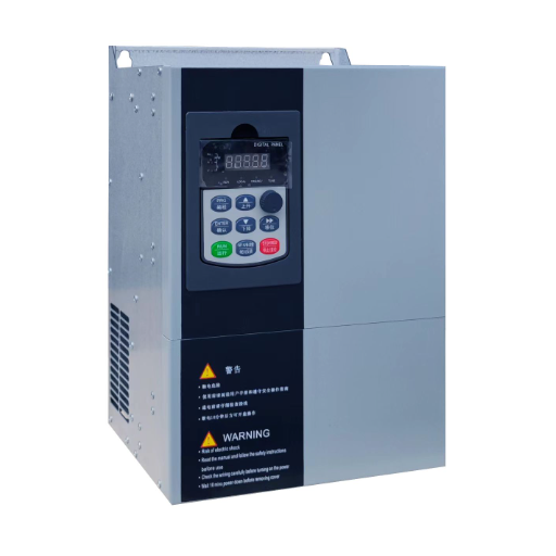
If you already have a standard drive and want closed-loop vector speed control with a pulse output, the YC-5000 low-voltage VFD publishes those features. It does not publish a built-in position loop or indexer, so the position loop still belongs in the PLC or in a drive with position firmware.
The encoder makes position control possible.
An incremental quadrature encoder outputs A and B pulses plus an index Z pulse. The drive counts edges to know how far the shaft moved, but it does not know where the shaft is at power-up. A 1024 PPR encoder is a common default. After four-times decoding, it gives 4096 counts per motor revolution.
An absolute encoder reports a unique position at power-up, so no homing is needed. Absolute encoders are available with SSI, EnDat, Hiperface, and other serial interfaces.
Use differential RS-422 drivers, shielded twisted pairs, and a separate pair for the index channel. Bond the shield at the drive end only, and keep the cable away from motor cables. One integrator’s guide puts the maximum length at about 50 ft (15 m) at 5 V and 100 ft (30 m) at 12 to 24 V.
Encoder resolution is the smallest position change the device can detect. Accuracy is the maximum deviation from the true position. A Nidec engineering guide makes the distinction directly: position accuracy is almost always lower than resolution. A 1024 PPR encoder gives 4096 counts per motor revolution. With a 5:1 gearbox and a 1.5 inch lead, that is about 13,653 counts per inch. One count is far finer than the mechanical system can hold, which is why a finer encoder rarely fixes a loose axis.
An incremental encoder needs a home reference. The common method is a home proximity switch followed by the first index pulse, which gives a repeatable zero point. An absolute encoder avoids the homing move, but it still needs a position offset if the mechanical zero is not the encoder zero. Document that offset. A new encoder or a replaced drive that loses the offset will put every target in the wrong place.
The tolerance you promise is the sum of every error source between the encoder and the load. One integrator’s encoder feedback guide lists the sources it sees in the field.
| Error source | Typical range | What to do |
|---|---|---|
| Mechanical backlash | 0.005 to 0.050 inch | Use a preloaded or zero-backlash drive; approach from one direction |
| Shaft wind-up and stretch | 0.001 to 0.020 inch | Use a rigid coupling; shorten the drive train |
| Drive scan and network latency | 4 to 20 ms equivalent | Use a hardwired stop input; keep the position loop in the drive |
| Friction and thermal drift | 0.001 to 0.010 inch | Warm up the machine; re-home after maintenance |
| Encoder quantization | About 1 count | Usually not the limiting error |
| Operator speed or decel change | Up to 0.5 inch | Lock the decel time; use a speed-to-decel recipe |
A finer encoder will not fix a loose gearbox. Fix the mechanics, then the feedback, then the tuning. A gearbox also multiplies encoder resolution at the load. One field guide reports about plus or minus 1/8 inch at 10:1, 1/16 inch at 25:1, and 1/32 inch at 40:1. Those are field observations, not guarantees. A 1:20 to 1:50 ratio is a common recommendation.
A position loop can only correct as fast as it sees the error. A hardwired digital input has about 5 to 10 ms of latency. EtherNet/IP implicit messaging runs about 10 to 30 ms, Modbus RTU about 20 to 60 ms, and explicit Ethernet about 20 to 80 ms. At 25 in/s, 30 ms of jitter equals 0.75 inch of position error. Send the final stop through a hardwired input.
The deceleration ramp is the other dominant error. A fixed decel time gives a repeatable stop distance. An operator-adjustable decel time gives a stop distance that changes with speed. The stop distance equals initial speed times decel time divided by two. Disable DC injection at stop because its fixed-frequency current pulse can drift the stopping point with load and temperature.
Take a 36-inch index with 0.7 s acceleration, 0.1 s at constant speed, and 0.5 s deceleration. Peak speed is distance divided by the sum of half the acceleration time, the constant-speed time, and half the deceleration time. That gives 51.4 in/s and about 18.3 cycles per minute. At 25 in/s and a 0.5 s decel, the stop distance is 6.25 inch. Place the sensor 6.25 inches before the target, adjust it to center the mean, and check the standard deviation over 50 dry cycles. A standard deviation below 0.020 inch is a common acceptance target for a plus or minus 1/16 inch window.
A position drive must deliver acceleration, deceleration, and holding torque, not just running torque.
Calculate the load inertia, the acceleration torque, and the RMS torque over the cycle, then add motor and gearbox inertia. Check the motor’s thermal capability at the actual duty cycle. Use an inverter-duty motor because a standard fan-cooled motor loses cooling at low speed. A VFD retrofit often needs a larger motor than the clutch-brake it replaces. One field guide reports that a 1 HP clutch-brake indexer may need a 1.5 HP VFD because the gear ratio is lower and the acceleration torque is higher.
Decelerating a load returns energy to the drive’s DC bus. A dynamic braking resistor turns that energy into heat. A regenerative drive feeds it back to the network. ABB’s position control program is available on regenerative drives, which matters on high-cycle axes.
A mechanical brake is a holding device, not a stopping device. ABB’s crane control manual says the brake holds the motor and driven machinery at zero speed when the drive is stopped or unpowered. It is not there to stop a moving load. The brake sequence must be interlocked with the drive. ABB’s crane example uses a 50 percent brake open torque, a 1 second open delay, and a 1 second close delay. Too short a delay can wear the brake or drop the load.
Kenji, a maintenance technician at a wire products plant, saw both failure modes on a hoist. On every start the load rolled back before the brake released. On every stop the brake grabbed before the drive reached zero speed. Proving torque before release and setting a brake close speed and delay fixed both.
Commission the axis in this order. Skipping a step usually shows up later as drift or a following-error fault.
If the axis has a mechanical brake, test it before you test position. A brake that releases late or closes early will make every position reading look wrong.
VFD position control works best on moderate-accuracy, moderate-cycle axes. The A3/MCMA article puts the practical band at 0.5 to 2 mm, or about 1.5 degrees. One integrator’s field data shows plus or minus 1/16 inch on a conveyor index with a 40:1 gearbox.
Good applications include conveyor indexing, rotary tables, crane and hoist positioning, packaging lines, machine tool carriages, cut-to-length feeds, and storage units. The A3 article names automated guided forklifts, hoists, smart conveyors, palletizers, and freight elevators. For conveyor-specific sizing, see our guide to conveyor belt drives.
A VFD is the wrong tool below about 0.1 mm, at high dynamic response, or on coordinated multi-axis motion. It is also a poor fit for a vertical load that must hold position without a brake. Those jobs belong to a servo or a dedicated motion controller. Our article on VFD vs servo drive gives the tolerance thresholds and cost comparison. A mechanical cam is still right when the motion is fixed and the cycle is fast.
Yes, if it has encoder feedback and a position loop in the drive or PLC. A standard V/Hz drive without feedback cannot hold position, and sensorless vector alone is not enough.
Yes, for a closed loop. The encoder tells the drive or PLC how far the load moved. Some drives offer encoderless positioning, but no source reviewed here publishes an accuracy figure for it.
About 0.5 to 2 mm, or 1.5 degrees, according to the A3/MCMA article. A well-geared conveyor index can repeat to plus or minus 1/16 inch. A servo reaches 0.01 mm, so the VFD band is not a servo replacement.
Only with closed-loop vector or comparable feedback, within the motor’s holding torque. A mechanical brake is safer for a vertical load or a long hold. A standard V/Hz drive cannot hold at zero speed.
A 25:1 to 40:1 gearbox is a common starting point for conveyor indexing. One field guide reports plus or minus 1/16 inch at 25:1 and 1/32 inch at 40:1. Check the output speed and cycle time before you choose the ratio.
Common causes are backlash, a changing decel ramp, network latency on the stop command, DC injection, a loose coupling, or a missing home offset. Fix the mechanics, lock the decel time, and use a hardwired stop input.
VFD position control is a feedback problem before it is a drive problem. Choose the loop location, specify an encoder, build the accuracy budget, and commission the axis in a fixed order. The drive matters, but gearing, backlash, and stop logic often decide the result.
For a moderate-accuracy axis, a closed-loop vector VFD with an encoder and a PLC or drive position loop is a practical, lower-cost alternative to a servo. For sub-0.1 mm work, high dynamics, or coordinated multi-axis motion, specify the servo.
Send the axis data to our engineers: load, gearbox, encoder, cycle time, and tolerance. We will tell you whether a VFD loop can hold it.