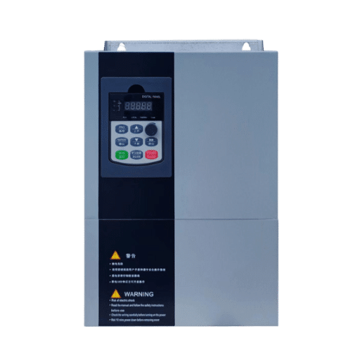
Ready to Get Your VFD Solution?
Whether you need a single drive or a complete system, we have the VFD products and engineering support to ensure your project's success.


An AC drive system is the complete chain of equipment that controls an AC motor’s speed: input conditioning, the drive itself (rectifier, DC bus, inverter), output filtering, the motor cable, the motor, feedback devices, and the supervisory control layer. The drive unit alone is only one link in that chain, and treating it as the whole system is the single most common specification mistake in the industry.
Here is why that matters in practice. Last year, a contractor named David installed a premium 75 kW drive at a pumping station outside Jinan. The drive was excellent. The 150-meter cable run to the motor had no output filter. Within five months, voltage reflections from the PWM waveform had chewed through the motor’s winding insulation, and the motor failed. The drive was never the problem. The system design was.
If you have ever specced, installed, or inherited an AC drive system, you already know the frustration of a “good drive” surrounded by a bad system. This guide explains every component from the supply terminals to the motor shaft, what each one does, and exactly what breaks when you leave one out. At Shandong Electric, we deliver complete drive solutions rather than standalone units, and this is the system map our engineers work from.
Key Takeaways
- An AC drive system is the whole chain: supply conditioning, drive, output filtering, cable, motor, feedback, and supervisory control. The drive box alone is not the system.
- Every skipped component has a predictable failure: no line reactor means harmonics, no output filter on a long cable means insulation damage, no braking resistor means overvoltage trips.
- Standard motors typically tolerate 30 to 50 m of drive-fed cable; inverter-duty motors stretch that to roughly 100 to 150 m before output filtering becomes necessary.
- A 3% line reactor typically cuts current harmonics from around 80% THDi down to 30 to 40%, protecting both the drive and the supply.
- Specification is a checklist, not a guess: motor compatibility, cable length, filtering, braking, feedback, control integration, and environment.

An AC drive system is a coordinated set of electrical components that takes fixed-frequency grid power, converts it to variable-frequency, variable-voltage output, and uses it to control the speed and torque of an AC motor. It includes the power supply connection, input filters and reactors, the AC drive unit, output filters where required, the motor cable, the motor itself, optional speed feedback devices, and the PLC or HMI layer that supervises the whole installation.
You will see the same hardware called an AC drive, VFD, VSD, or ASD depending on the catalog. They are the same device; our guide to AC drive, VFD, and VSD naming explained covers the terminology if you need it.
The insight to carry through this entire AC drive system explanation is simple: the drive is one component of the system, not the system itself. Every other link in the chain affects whether the drive performs as its datasheet promises.
The table below is the whole article in one view. Each row names a component, its function, and the specific failure you invite by omitting it.
| Component | Function | What Happens Without It |
|---|---|---|
| Power supply connection | Delivers fixed-frequency AC (50/60 Hz) to the system | Nothing runs; supply quality issues propagate downstream |
| Line reactor / DC choke | Smooths input current, limits harmonics | Supply distortion; THDi near 80%; premature rectifier wear |
| EMC filter | Suppresses radio-frequency interference | Interference with nearby instruments and communications |
| The AC drive (rectifier, DC bus, inverter) | Converts fixed AC to variable-frequency output | This is the core; without it there is no speed control |
| Braking resistor | Absorbs regenerative energy during deceleration | DC bus overvoltage trips, typically at 750 to 800 V on 400 V-class drives |
| dV/dt or sine filter | Softens the PWM output waveform | Motor insulation stress and bearing currents on long cables |
| Motor cable | Carries drive output to the motor | Reflections and losses grow with length; shielding errors cause EMI |
| AC motor | Converts electrical energy to shaft rotation | Standard motors overheat or fail early on unfiltered drive power |
| Encoder / feedback device | Reports actual shaft speed and position | Speed drift under varying load; no true closed-loop control |
| PLC / HMI / SCADA | Supervises setpoints, alarms, and data | No automation integration; manual control only |
Now let us walk the chain in the order power actually flows.
Everything starts at the supply terminals. The drive expects clean, balanced three-phase power, and the input side exists to protect both the drive from the grid and the grid from the drive.
A line reactor (or a DC choke inside the drive) adds impedance that smooths the current the rectifier draws. A 3% impedance reactor typically brings total harmonic current distortion down from around 80% THDi to 30 to 40%, which matters for IEEE 519 compliance and for the life of the drive’s own capacitors.
The EMC filter handles a different problem: high-frequency noise that rides the power lines and radiates from cables. Skip it, and nearby sensors, radios, and instrumentation start misbehaving in ways that are miserable to diagnose.
Inside the drive, three stages do the conversion. The rectifier turns incoming AC into DC. The DC bus, a bank of capacitors, smooths and stores that energy. The inverter, built from IGBTs switching thousands of times per second, synthesizes a variable-frequency PWM output that the motor reads as clean AC.
Modern AC drives run 96 to 98% efficiency through this chain, and their soft-start behavior cuts motor inrush from 6 to 8 times full-load current down to roughly 1 times. For the full electronics deep-dive, see our article on the VFD working principle in detail. Here, what matters is the drive’s role in the system: it is the controllable valve between the grid and the motor.
The inverter’s PWM output is a chain of very fast voltage steps, with rise times short enough to produce dV/dt rates that stress motor insulation. Over a short cable, the motor absorbs this. Over a long cable, the pulses reflect at the motor terminals and stack to nearly double their amplitude.
This is where the cable-length thresholds come in. Standard motors on PWM drives typically tolerate around 30 to 50 m of cable before a dV/dt filter is advisable. Inverter-duty motors, built with reinforced insulation, stretch that to roughly 100 to 150 m. Beyond that, a sine filter, which reconstructs a smooth sinusoidal waveform, is the safer choice.
The motor is part of the AC drive system, not a passive attachment. Drive-fed motors need insulation rated for PWM voltage spikes (inverter-duty per NEMA MG1 Part 31 is the common benchmark), adequate cooling at low speed where the shaft fan moves less air, and attention to bearing currents.
Bearing currents are the quiet killer. Common-mode voltage from the drive induces a shaft voltage that discharges through the bearings, pitting the races over months of operation. EASA documents the failure pattern extensively. Mitigation options include insulated bearings, shaft grounding rings, and, on long cable runs, the output filters already discussed.
Open-loop control estimates motor speed from output frequency and measured slip, which is accurate to roughly ±0.5% under changing load. That is fine for fans and pumps. It is not fine for winders, hoists, or positioning duties.
An encoder mounted on the motor shaft closes the loop: the drive compares commanded speed against measured speed and corrects in milliseconds. With closed-loop vector control, speed regulation tightens to about ±0.01%, and full torque becomes available at or near zero speed.
The top layer is where the system joins the plant. Over fieldbus links such as Modbus or Profibus, a PLC sends speed setpoints and start/stop commands to the drive, while the drive reports current, torque, temperature, and fault codes upward. The HMI turns that data into something an operator can act on at 2 a.m.
Our low voltage VFD systems support the standard industrial protocols, so this integration layer is usually a configuration task rather than an engineering project.

Here is the full power and signal flow, step by step:
Two things happen in parallel throughout: the drive’s control algorithm (V/f, sensorless vector, closed-loop vector, or DTC) decides what the inverter should do next, and the protection layer watches current, voltage, and temperature for anything out of bounds.
Each omission from the master table has a signature failure. These are the four we see most often in the field.
No line reactor. Harmonic currents distort the plant supply, overheating transformers and tripping sensitive equipment. The drive’s own DC bus capacitors age faster under the current peaks.
Long cable, no output filter. Reflected-wave voltage spikes erode winding insulation, and bearing currents pit the bearing races. This is exactly what happened in David’s pumping station from the introduction. The fix was not a new drive. It was a dV/dt filter at the drive output, plus a shaft grounding ring on the replacement motor. That installation has now run two years without a single insulation fault.
No braking resistor. A water treatment plant we supported kept tripping on overvoltage every time its 45 kW transfer pump ramped down. The high-inertia impeller pushed energy back into the DC bus, which climbed past 780 V and tripped the drive. A correctly sized braking resistor absorbed the regenerative energy, and the trips stopped the same week.
No encoder on a precision load. A packaging line running open-loop drifted as much as 2% under varying product weight, which was enough to misalign seals. Adding an encoder and switching to closed-loop vector control held speed within ±0.01%, and the misaligned-seal rejects dropped to zero.
Older plants sometimes still run DC drive systems: a DC motor with a controlled rectifier supplying its armature. DC drives offer excellent low-speed torque and simple control, which is why they dominated variable-speed applications for decades.
Industry standardized on AC for three reasons. AC induction motors are cheaper, more rugged, and nearly maintenance-free compared to brush-and-commutator DC motors. AC drives are more efficient across the load range. And modern vector control has erased the old performance gap, matching DC torque response in all but the most specialized applications.

When you scope a new installation or audit an existing one, walk this list in order:
For the drive selection itself, see our guide to selecting the right VFD. For grounding, shielding, and commissioning detail, our industrial VFD system installation guide picks up where this checklist ends.
Yes. AC drive, variable frequency drive (VFD), variable speed drive (VSD), and adjustable speed drive (ASD) all describe the same class of device. The industry uses the terms interchangeably, with regional and vendor preferences deciding which one appears on the nameplate.
No. The drive and the motor are separate components, and the drive is sized to match a specific motor’s voltage, current, and application demands. A complete AC drive system includes both, plus the conditioning and control components covered above.
Standard three-phase induction motors are the most common pairing, and modern drives also run permanent magnet and synchronous reluctance motors. The motor should be inverter-duty rated or protected by appropriate output filtering, especially on longer cable runs.
Not always, but the decision should be deliberate rather than default. Short cables, clean supplies, and light harmonic budgets can skip both. Long cables, weak supplies, or sensitive neighboring equipment make them essential. The thresholds in this article give you the starting points.
An AC drive system succeeds or fails as a chain. The input conditioning protects the power quality, the drive does the conversion, the output filtering protects the motor, the cable and motor deliver the work, and the feedback and supervisory layers keep everything honest. Remove any link, and you get a predictable, expensive failure mode.
The good news is that system-level thinking is a checklist, not a mystery. Motor compatibility, cable length, filtering, braking, feedback, integration, environment. Walk those seven items, and the system will perform as a unit.
If you would rather have engineers walk it with you, that is what we do. Shandong Electric supplies complete drive solutions, from the drive itself through filtering, cabinets, and commissioning support. Contact our engineering team → with your motor data and cable runs, and we will spec the whole chain, not just the box.