Ready to Get Your VFD Solution?
Whether you need a single drive or a complete system, we have the VFD products and engineering support to ensure your project's success.
A VFD for pumps and fans reduces energy consumption by 30 to 70 percent by matching motor speed to actual demand instead of throttling flow with valves or dampers. For any centrifugal pump or fan operating at partial load, a variable frequency drive is the single highest-ROI upgrade you can make.
You already know energy costs are rising and maintenance budgets are tight. What you need is an honest breakdown of how variable frequency drive pump control and fan speed control actually work, where the two applications diverge, and how to size and configure a drive without guessing. If you are new to variable frequency drives, our overview of 3-phase VFD solutions explains the fundamentals. This guide covers exact sizing rules, PID parameter starting points, minimum speed limits, and real payback numbers you can use on Monday morning.
Key Takeaways
- A 20% speed reduction cuts power consumption by roughly 50% on centrifugal pumps and fans thanks to the affinity laws.
- Pumps and fans are variable torque loads, so size the VFD for Normal Duty (110-120% overload), not Heavy Duty.
- Pump control must respect NPSH and minimum flow; fan control must avoid windmilling and duct pressure spikes.
- Closed-loop PID control captures 30-50% more savings than manual speed setting on variable-load systems.
- Typical payback for pump and fan VFD retrofits is 6 to 24 months, with utility incentives covering 20-50% of equipment cost.
For a deeper dive on single-phase input configurations, see our guide to single phase vfd guide

A VFD for pumps and fans is a variable frequency drive that controls motor speed to match real-time demand in fluid and air handling systems. By adjusting motor frequency and voltage, it eliminates mechanical throttling, cuts energy use by 30-70%, and extends motor life.
Need help selecting the right drive for your pump or fan? Our VFD sizing guide walks you through FLA matching, load-type confirmation, and real-world derating.
Pumps and fans represent roughly 60% of all industrial motor applications worldwide. That scale alone makes them the most important target for energy-saving motor control. For building automation and climate systems specifically, our HVAC VFD solutions cover AHU, cooling tower, and exhaust fan configurations. The reason VFDs work so well here is physics, not marketing.
Centrifugal pumps and fans follow the affinity laws. Torque is proportional to the square of speed. Power is proportional to the cube of speed. That cubic relationship is what makes VFD energy savings so dramatic.
A small drop in motor speed creates a large drop in power draw. At 80% speed, a pump or fan consumes roughly 51% of full-load power. At 50% speed, it drops to just 12.5%. Compare that to throttling a valve or damper, which keeps the motor at full speed and simply wastes the excess energy as heat and noise.
| Speed (%) | Flow (%) | Power (%) | Energy Saved |
|---|---|---|---|
| 100% | 100% | 100% | 0% |
| 80% | 80% | 51% | ~49% |
| 60% | 60% | 22% | ~78% |
| 50% | 50% | 12.5% | ~87.5% |
This table is why a VFD for pumps and fans pays for itself faster than almost any other industrial upgrade. The motor still runs, but it only works as hard as the system actually demands.
Not every pump is a centrifugal pump. Not every load behaves the same way. The distinction matters because it determines how you size the VFD.
Centrifugal pumps and axial/centrifugal fans are variable torque loads. The drive only needs to deliver 110-120% overload capacity for 60 seconds. Positive displacement pumps, piston pumps, and gear pumps are constant torque loads. They need Heavy Duty rating, typically 150% overload for 60 seconds.
If you install a Normal Duty VT drive on a positive displacement pump, the drive will trip on overload the first time discharge pressure spikes. Always confirm your pump type before you select the VFD duty rating.
A VFD for pumps and fans must account for completely different system dynamics even though both follow the same quadratic load curve. Treat them the same way and you will either cavitate a pump or trip a fan drive.
A pump must overcome static head plus friction head in the piping system. Static head is constant. Friction head increases with flow. The system curve is a parabola starting above zero.
When you slow a pump with a VFD, two risks appear. First, if speed drops too far, net positive suction head (NPSH) may fall below the pump requirement. That causes cavitation, impeller damage, and seal failure. Second, every pump has a minimum continuous flow to prevent overheating from recirculation inside the volute.
The baseline comparison for pump energy savings is valve throttling. A partially closed control valve dissipates energy across the restriction while the motor runs at full speed. A VFD eliminates that waste by slowing the motor directly.
Fans operate against static pressure in ducts and plenums. The system curve is also quadratic, but the baseline comparison is different. Most HVAC fans were originally controlled with outlet dampers or inlet guide vanes.
Dampers are slightly more efficient than valves at partial load, but they still waste enormous energy compared to speed control. A VFD fan speed control system modulates airflow by changing RPM, which follows the cubic power curve.
Fans have their own unique risk: windmilling. If system pressure spins the fan blade while the motor is off, the VFD must not attempt to start into a back-spinning load. Some drives offer fly-start detection, but the safer approach is to program a minimum speed above the windmilling threshold or add a mechanical backdraft damper.
| Factor | Pump Control | Fan Control |
|---|---|---|
| Baseline waste | Valve throttling | Damper / IGV restriction |
| Minimum speed limit | NPSH cavitation + min flow | Motor cooling + windmilling |
| Critical failure mode | Cavitation, dry running | Duct overpressure, back-spin |
| Sensor location | Diff pressure across remote load | Duct static pressure ~2/3 downstream |
| Sleep/wake risk | Deadheading, dry run | Zero airflow, CO buildup |
Understanding these differences is what separates a working installation from an optimized one.
Sizing a VFD for pumps and fans follows the same FLA-first methodology as every other application, with one extra check: confirming the load torque profile.
Start with the motor nameplate. You need voltage, full load amps, base frequency, service factor, and insulation class. For variable frequency drive pump control, FLA is the number that matters. Horsepower is a convenient label, but current determines heat in the VFD power stage.
If you are working with single-phase input drives, our single-phase VFD wiring guide covers grounding, breaker sizing, and EMI filtering.
Match the drive continuous output current rating to the motor FLA. If the motor service factor is 1.15 and your process pushes into that range, size to service factor amps or add 10-15% headroom.
Check that the drive is listed for Normal Duty or Variable Torque duty. Most general-purpose VFDs support both VT and CT profiles, but the overload rating and default parameters differ.
Normal Duty means 110-120% overload for 60 seconds. Heavy Duty means 150%. A centrifugal pump or fan should run in Normal Duty mode.
If you are unsure whether your pump is centrifugal or positive displacement, err on the side of Heavy Duty. The only penalty is a slightly larger frame size and higher cost.
Real installations are rarely textbook when you size a VFD for pump or fan duty. Apply these derating factors before you finalize the model:
| Motor HP | FLA (230V) | FLA (460V) | Min VFD Rating (VT) |
|---|---|---|---|
| 5 HP | 22 A | 11 A | 120% of motor FLA |
| 10 HP | 40 A | 20 A | 120% of motor FLA |
| 25 HP | 92 A | 46 A | 120% of motor FLA |
| 50 HP | 178 A | 89 A | 120% of motor FLA |
| 100 HP | 344 A | 172 A | 120% of motor FLA |
For low voltage VFD systems below 690V, these rules apply directly. Medium voltage drives need separate engineering review.
How you control the VFD matters almost as much as which VFD you buy. A poorly controlled drive sacrifices 30 to 50 percent of the energy savings that the affinity laws promise.
Open-loop means you set a speed reference manually or on a fixed schedule. The VFD runs at 45 Hz all day, or drops to 35 Hz on the night shift. No sensor feedback. No automatic adjustment.
This approach works when load is predictable. A irrigation pump that only needs two flow rates, or an exhaust fan on a fixed timer, can run open-loop successfully. The hardware cost is lower because you skip sensors and PID configuration.
The downside is waste. If demand changes and the speed does not, you are throttling mechanically again. Open-loop is a stepping stone, not a destination, for most commercial and industrial systems.
Closed-loop PID is where VFD energy savings pumps fans results get serious. A sensor measures the process variable. The VFD compares it to the setpoint and adjusts speed automatically.
For pumps, install a differential pressure sensor across the most remote load in the piping network. As zone valves close, pressure rises and the VFD slows the pump to maintain setpoint. For fans, place a static pressure sensor roughly two-thirds of the way down the longest duct run. As dampers close, pressure rises and the fan slows.
Here are practical PID starting parameters for pump and fan VFD control:
| Parameter | Pump Pressure PID | Fan Static Pressure PID |
|---|---|---|
| Proportional gain (P) | 0.5 – 2.0 | 1.0 – 3.0 |
| Integral time (I) | 2 – 10 seconds | 1 – 5 seconds |
| Derivative time (D) | 0 (disable) | 0 (disable) |
| Minimum output frequency | 20-30 Hz (NPSH limit) | 15-25 Hz (cooling limit) |
| Acceleration time | 5-15 seconds | 10-30 seconds (high inertia) |
| Deceleration time | 5-15 seconds | 10-60 seconds (prevent duct spike) |
Start conservative. A slow, stable loop beats a fast, oscillating loop every time. Oscillation causes hunting, mechanical stress, and premature valve wear.
When Marcus took over the municipal water plant in Ohio, his distribution pumps ran at full speed 24 hours a day. A throttle valve downstream choked flow to match demand. After installing differential pressure sensors and PID-capable VFDs, daily energy dropped 57 percent. The project paid for itself in 16 months, and the valves stopped wearing out.
Large systems often need multiple pumps or fans. A single oversized VFD is rarely the right answer. Staging multiple smaller drives gives redundancy and better part-load efficiency.
Lead-lag pump control alternates which pump runs first to equalize runtime. As demand rises, a second pump stages on. As demand falls, it stages off.
Some VFDs include built-in multi-pump functions. Others need a small PLC to handle staging logic. For systems below 690V, our low voltage VFD systems overview explains integrated pump/fan functions, communication options, and staging software.
For cooling tower cells or AHU arrays, the same principle applies. Run each fan at its most efficient speed, and only bring additional units online when the running units approach maximum speed.
Modern drives include pump-specific software functions that add savings beyond speed control. Sleep mode stops the motor when demand drops below a minimum threshold, then wakes it automatically when pressure or flow calls for it.
Dry-run protection monitors power draw. If the pump runs without fluid, power drops sharply and the VFD faults out before seal damage occurs.
Auto voltage optimization reduces motor voltage at partial load. It squeezes an extra 5 to 15 percent savings with no hardware changes.

The affinity laws work in both directions. Just as power drops at low speed, cooling airflow drops too. A standard TEFC motor relies on its shaft-mounted fan. At 15 Hz, that fan moves a fraction of the design airflow.
Motor insulation classes are rated based on maximum winding temperature. When cooling drops, temperature rises. If the motor is also loaded heavily at low speed, the combination can push winding temperatures past the insulation limit.
Pumps add a second constraint. Below a certain speed, NPSH available from the suction tank or well drops below NPSH required by the pump. Cavitation begins. Impeller damage follows within weeks.
Fans add a third constraint. Windmilling speed is the RPM at which system airflow spins the blade backward. Starting into a windmilling load creates a current spike that trips the drive.
| Motor Poles | Base Speed (60 Hz) | Min Speed TEFC (Continuous) | Min Speed Forced Ventilation |
|---|---|---|---|
| 2-pole | 3,600 RPM | 720-900 RPM (12-15 Hz) | 360-540 RPM (6-9 Hz) |
| 4-pole | 1,800 RPM | 360-450 RPM (12-15 Hz) | 180-270 RPM (6-9 Hz) |
| 6-pole | 1,200 RPM | 240-300 RPM (12-15 Hz) | 120-180 RPM (6-9 Hz) |
| 8-pole | 900 RPM | 180-225 RPM (12-15 Hz) | 90-135 RPM (6-9 Hz) |
For pump applications, cross-check the mechanical minimum against the NPSH curve. The higher of the two limits wins. For fan applications, verify windmilling threshold experimentally or consult the fan manufacturer. When in doubt, use an infrared camera on the motor bearings and windings after 30 minutes of continuous operation at your programmed minimum.
VFD energy savings pumps fans applications deliver the fastest payback in industrial automation. The combination of high run hours and cubic power reduction creates math that is hard to argue with.
| Application | Typical Load Range | Expected Energy Savings |
|---|---|---|
| HVAC supply/return fans | 40-70% | 35-50% (up to 65% with integrated controls) |
| Centrifugal pumps | 50-80% | 30-45% (up to 70% in ideal conditions) |
| Cooling tower fans | 30-60% | 40-60% |
| Process blowers | 60-85% | 25-40% |
| Water distribution pumps | Variable | 30-57% |
These percentages assume the VFD replaces mechanical throttling or damper control. If the baseline is already a VFD running open-loop, upgrading to PID control will still capture 30 to 50 percent more savings.
Annual savings equals energy reduction multiplied by run hours multiplied by cost per kilowatt-hour. Add maintenance savings from reduced mechanical wear. Subtract any incremental maintenance for the VFD itself.
A typical retrofit payback runs 6 to 24 months. The range depends on run hours and local electricity rates. A 100-horsepower HVAC supply fan running 6,000 hours per year at 0.12perkilowatt−hourcansaveroughly0.12perkilowatt−hourcansaveroughly43,000 annually with a 60 percent energy reduction.
Utility incentive programs commonly cover 20 to 50 percent of installed equipment cost for qualifying pump and fan VFD retrofits. Most programs require automatic closed-loop control, minimum annual run hours, and pre/post metering verification.
When the engineering team at a Dubai restaurant chain added CO-based VFD fan speed control to their kitchen exhaust systems, ventilation energy dropped 32 percent. The fans had run at full speed for 16 hours a day regardless of how many stoves were active. The VFDs paid for themselves in under a year.
Ready to compare drives by price tier and application? See our buyer’s guide to 3-phase VFDs for budget, mid-range, and premium recommendations.
Even experienced engineers make these errors when applying a VFD for pumps and fans. Learn from them so you do not repeat them.
1. Using a VT drive on a positive displacement pump. A gear pump or piston pump needs constant torque and 150% overload headroom. A Normal Duty VFD will trip repeatedly and eventually fail.
2. Ignoring minimum speed and burning up the motor. David in Kentucky installed a VFD on a 20-horsepower chiller pump and programmed a 10-hertz minimum because that is what worked on his last job. That last job was a fan. The chiller pump was positive displacement.
The motor overheated in two weeks because the pump could not move enough fluid at low speed to cool itself.
3. Running a VFD without PID on a variable-load system. Manual speed control on a VAV air handler or variable-flow chilled water system leaves 30 to 50 percent of potential savings on the table. The hardware is already installed. The sensor costs less than $200.
There is no excuse.
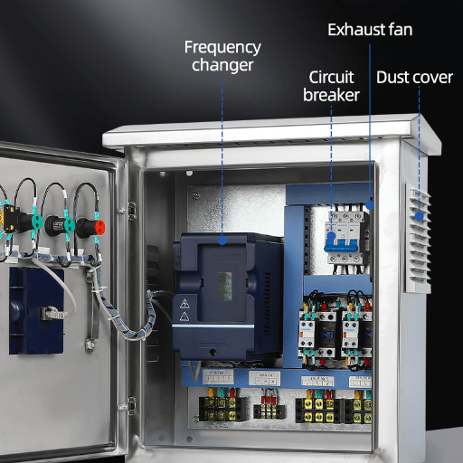
4. Forgetting harmonic mitigation in multi-VFD plants. A mechanical room with eight VFDs on one transformer can push total harmonic distortion past IEEE 519 limits. Add 3% line reactors or DC link chokes to every drive. For plants with 12 or more drives, budget for an active harmonic filter.
5. Using non-inverter-duty motors on long cable runs. Standard motor insulation is rated for 1,600 volts peak. VFD output switching creates voltage spikes that can reach 2,000 volts or more on long cables. Either use inverter-duty motors with reinforced insulation, or install dv/dt filters or sine wave filters on the VFD output.
6. Setting acceleration too fast on high-inertia fans. A large cooling tower fan or industrial exhaust blower has enormous inertia. Slamming it to full speed in 3 seconds pulls current well above the drive rating. Use 10 to 30 second acceleration ramps and verify the drive current profile during startup.
Can any VFD run a pump or fan?
Technically yes, but not optimally. A general-purpose VFD will spin the motor. For best results, choose a drive with built-in PID, pump-specific functions like sleep/wake and dry-run protection, and VT duty rating. This ensures the VFD for pumps and fans operates safely and efficiently.
What is the best control mode for a pump VFD?
Closed-loop PID with differential pressure feedback is the gold standard for pump systems. It maintains constant pressure automatically while minimizing energy consumption. For simple systems with fixed schedules, open-loop speed control is acceptable but less efficient.
How much can a VFD save on a 50 HP cooling tower fan?
Cooling tower fans typically save 40 to 60 percent when converted from cycling or damper control to VFD speed control. At 50 horsepower, 4,000 run hours per year, and 0.12perkilowatt−hour,thatisroughly0.12perkilowatt−hour,thatisroughly9,000 to $13,000 in annual electricity savings.
Do I need a braking resistor for a pump or fan?
Usually not. Centrifugal pumps and fans have low regenerative inertia. The VFD DC bus rarely overvolts during deceleration. If you have a very high-inertia fan that must stop in under 10 seconds, calculate the regenerative energy. Most pump and fan applications coast to a stop without a resistor.
Can one VFD control multiple pumps?
One VFD can control multiple pumps through staging logic, but only one pump runs on the VFD at a time. The others run across-the-line or through soft starters. True multi-pump control requires either a VFD with built-in staging software or an external PLC.
What is the lowest safe speed for a centrifugal pump?
The lowest safe speed is the higher of two values: the motor cooling limit and the pump NPSH limit. For a standard 4-pole TEFC motor, do not run below 12 to 15 hertz continuously without forced ventilation. For the pump, consult the manufacturer NPSH curve at your suction conditions.
A VFD for pumps and fans is not a niche upgrade. It is the standard for modern fluid and air handling systems. The affinity laws guarantee that reducing speed reduces power consumption by the cube. The only question is whether your installation captures that savings safely and completely.
Size by FLA, not horsepower. Confirm variable torque duty for centrifugal equipment. Set minimum speed limits that protect both the motor and the pump or fan.
Use closed-loop PID control on any system with variable demand. And always account for harmonics when multiple drives share a power bus.
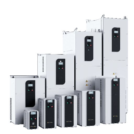
At Shandong Electric, we design and manufacture VFDs for the full spectrum of pump and fan applications, from compact low-voltage drives for HVAC retrofits to high-performance systems for water treatment and industrial process control. If you are evaluating variable frequency drive pump control or fan speed control for your facility, browse our pump and fan VFD range or contact our engineering team. We will help you size it right, configure it correctly, and capture every kilowatt of savings available.