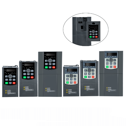
Ready to Get Your VFD Solution?
Whether you need a single drive or a complete system, we have the VFD products and engineering support to ensure your project's success.

Appropriate cable sizing and wiring of Variable Frequency Drives (VFDs) is amongst the most important aspects in terms of getting a good performance, safety, and energy-related issues in industrial and commercial applications. The use of Variable Frequency Drives to control motor speed and energy consumption has been growing, so it is vital that you have the primary things related to cable selection and installation right. This paper will take you through the most important points of choosing the right cable size, knowing the main aspects like voltage rating, current carrying capacity, and thermal abilities, as well as dealing with possible problems like harmonic distortion and electromagnetic interference (EMI). At the end of the article, you will be able to make decisions and have a planned course of action for your VFD wiring which would, in turn, protect your machines, reduce energy wastage and, very importantly, maintain high operational reliability.

It is very important for Variable Frequency Drives (VFDs) to have the right size of cable so that they can work efficiently, avoid getting too hot, and be a reliable part of the system. Cables that are too small can cause the voltage to drop too much, the energy losses to be higher, and the system to be overheated – a condition that can lead to damaging the equipment or shutting down the system. Very Large cables, on the other hand, can be a cause of extra expense and even installation problems. Correctly sized cables fit the current demand of VFDs; the space between the VFD and the motor is one of the reasons for the correct size, and the climatic conditions near the cables also play a role. Apart from the aforementioned, cables sized properly take care of the problems such as harmonic interference and noise and thus make the operation ideal in every manner as well as the electrical standards being met.
For the system to be secure and dependable, one must strictly adhere to the technical requirements upon selecting cables for Variable Frequency Drives (VFDs). The most important of all factors is the voltage rating, with the cable used having to be able to match or exceed the operational voltage of the VFD system. Any rating lower than that might lead to insulation failure and then to potential hazards. Moreover, the cable’s ampacity-that is, its ability to conduct current under the given conditions, needs to be able to fully carry the motor’s load current, taking into account the ambient temperature and the group connection or use in the confined area of the cable.
Electromagnetic Interference (EMI) is greatly decreased due to shieldings that are properly implemented. When shieldings, such as materials like braided copper or metallic foil, are used efficiently, harmonic distortion is reduced and at the same time, interference to the neighboring systems is effectively prevented at the source. The cable’s grounding and bonding methods are likewise, to be attended to with the greatest care, as they have a direct impact on people and equipment protection. Voltage drop must be calculated when it comes to long cabling, as too much attenuation can lead to worse energy consumption and motor performance. Actually, it is also necessary to check if the installation is in compliance with local codes such as the National Electrical Code (NEC) or International Electrotechnical Commission (IEC) standards to avoid safety hazards and ensure legal compliance.
Selection of the right-sized cable for drives that are connected to Variable Frequency Drives (VFDs) is very important and has to consider a lot of factors. One of the main issues is the current-carrying capacity of the conductor which must be very good to prevent the current flow from heating up the conductor. The voltage rating is also of paramount importance as the insulation of the cable should be strong enough to withstand the voltage spikes that are produced in VFD operation.
The cable length is also a significant consideration as it affects the efficiency of the circuit. The longer the cable length, the higher the resistance and inductance and, in turn, the greater the voltage drop and motor winding overheating. Therefore, the usual steps taken to circumvent this issue are either to go with cables of less resistance or to step up the size of the conductor. For the purposes of high-powered jobs, shielded cables to shield against electromagnetic interference (EMI) created by VFD systems, which is a common source of annoyance and trouble for the equipment with close-by delicate circuits, are sometimes the only solution.
Cable sizing is further influenced by ambient temperature and installation conditions, as these are part of the thermal aspects. This means that the cable ampacity has to be derated based on the ambient temperature to make sure that the cable will even operate in the elevated temperature condition or when several cables are bundled up together. For a precise adjustment of cable sizing, engineers have to rely on the temperature correction factors as provided in the standards such as the NEC or IEC.
For Variable Frequency Drives (VFDs) cable sizing requires a great deal of care to prevent damage to the equipment and to keep operational efficiency at its peak. The choice of cables for VFD usage should take into consideration, among other things, both the continuous current capability and the effect of harmonics generated by the drive. Harmonics cause an increase in cable heating; thus, cables with a higher temperature rating or with increased thermal resistance must be used. Often, the use of shielded cables is suggested to combat electromagnetic interference (EMI), which can have an adverse effect on the sensitive equipment in the vicinity.
Moreover, the cable’s insulation type and voltage rating ought to match the VFD’s characteristics, so it must be ok to use a cable that can very well handle switching pulses of high frequency which, without such a measure, could result in insulation failure prematurely. IEEE 519 and manufacturer guidelines are two of the numerous sources that can give information about the maximum allowable voltage drop and harmonic distortion, which in turn would decide the decisions that the engineers could make. Inducting cables properly requires the same measure of correction factor for different installation methods, bundling, and ambient conditions that directly affect the current-carrying capacity. System life, risk reduction in operations, and better electrical system performance can all be achieved by engineers through the use of these detailed considerations.
Voltage rating of VFD cables is an important factor that affects the performance of a system directly and also the safety of electricity usage. This is why when choosing the cables for VFD systems, it’s a must to pick the ones that are rated for the voltage the drive and the load needs, that is between 600V and 2kV or maybe more for industrial applications. Cables with a higher voltage rating give an additional layer of insulation that is definitely needed to prevent problems like those arising due to partial discharge and corona effect in high-frequency setups. Besides this, the cables must go through a series of tests during which they need to be proven to be capable of tolerating transient voltage peaks induced by the very fast switching process in the VFD, where pulse-width modulation (PWM) is the most applied.
Standards in place, such as the IEC 60502 and UL 1277, do set the minimum voltage criteria for cables in order to keep their quality up to the mark as requested by the tough safety and life expectancy needs. Moreover, it is very important to take into account derating factors which are penalties associated with environmental conditions like high temperature or cable bundling if the desired level of functional reliability is to be met. If the proper voltage buffer margin cable is chosen, keeping long-term operational stability and low chances of insulation failure or damage brought about by the stresses of voltage that come out of the system in some instances are the results that can be expected.
One of the crucial factors that greatly affect the choice of Variable Frequency Drive (VFD) cables is the current-carrying capacity or the so-called ampacity. In a way, the ampacity sets the limit of the current a cable can safely carry without going higher than the temperature that the cable is rated for. Thus, a correct assessment of this parameter guarantees the safety of the system and the prevention of cable faults due to overheating. For VFD uses, it is a must to think about the long-lasting working conditions and the momentary peak loads as well.
Making a proper evaluation of the power rating is a complicated process as we need to take into account a number of factors including the size of the conductor, ambient temperature, the method of installation (either buried, in the open air, or in a conduit) and the grouping of the cables. If cables are bundled, then derating factors have to be applied because the heat dissipation is limited which in turn has a big effect on the performance of the cables. Among the various references that give detailed guidelines for the calculation of the ampacity under different sorts of installations, the National Electrical Code (NEC) and the International Electrotechnical Commission (IEC) standards are very essential. Furthermore, the use of the advanced materials for the sheath purpose like cross-linked polyethylene (XLPE) has often been seen to augment the cable’s thermal strength that allows them to bear the high-current conditions without showing any degraded performance.
The choice of VFD cables calls for a judicious selection in terms of the operating conditions and environmental factors so as not only to guarantee the reliability of the system but also its long service life. The most commonly used VFD cables are those that are subjected to wide thermal ranges, from very cold to very hot, throughout the time they are being used. This kind of condition can cause the insulation materials to either decay over time or the conductors to be oxidized. The latest design paradigms suggest the use of top-notch materials like thermoset insulations or polymer blends which provide the desired thermal resistance, thus the performance in a broad temperature range, typically from -40°F (-40°C) to 194°F (90°C) depending on the class of material.
Except for the heating issue, wetness, oil, and other substances from chemicals might still cause certain problems to VFD cables that are not so long-lasting. Choosing the cables that are provided with such sheath compounds as chlorinated polyethylene (CPE) or polyurethane (PUR) of high quality is one of the effective ways to deal with the aforementioned issues. For outdoor settings or places with high exposure, UV resistance is essential to prevent decay as a result of prolonged sunlight. There are IP-rated cables, which are rated at certain ingress protection (IP) levels, for these products in the groups, for instance, they are sealed well against harsh conditions like no particle matter or even liquid can penetrate. Therefore, cable selection based on these high environmental standards is paramount to ensure the factory is operating with maximum efficiency and can confidently meet the industry standard for reliability.

For all motors, you must shield with a grounded shield that is properly rated to minimize electromagnetic interference (EMI), which in turn can disturb the electronics that are nearby. The mentioned cable shield should be grounded at both the motor and drive ends in a consistent manner.
To avoid crosstalk and keep noise interference low, one should always run the VFD cables independently of other power and control wiring. A distance of 12 inches at least is commonly recommended.
In order to avoid stray currents and make the system safe by all means, ground the motor, drive, and enclosure components as well.
It is recommended to always have the shortest motor cable lengths possible. Minimize the risk of voltage drops and reflections. However, if long cables are still inevitable, then the usage of output reactors and filters shall be considered.
The guidelines the VFD manufacturer provides for both wiring and installation should always be followed. From a performance and warranty standpoint, this is the surest way to go.
Electromagnetic radiation (EMI) happens whenever variable frequency drives (VFDs) are applied and this is a necessary concern that one has to deal with not only to avoid disturbance to sensitive equipment but also to comply with electromagnetic compatibility (EMC) standards. The best-known procedure for EMI reduction is proper grounding and shielding. Make sure that the low impedance grounding connections are applied to all VFDs, as this has a large influence on the increase of EMI due to lack of proper grounding. Apart from that, it is mandatory to use shielded cables for the motor connections. The cables must be such that they have complete shielding, with shields properly terminated at both ends to ensure the highest possible level of efficiency.
A solution to cut EMI further would be to put up line filters or chokes between the VFD and the power supply in order to reduce conducted and radiated interference to a minimum. One more good measure is to have the VFDs and the wires that are in connection with it placed away from communication lines and sensitive electronics. Enclosures having EMI-gaskets are able to deliver the extra isolation in the cases where it is needed. The last piece of advice is to follow strictly the right EMC standards and to think of turning to consulting companies that know, for example, the IEC 61800-3, and are to the point in method specifics of application requirements. So, by applying those principles, the users can simultaneously cope with the EMI issues, ensure the system’s reliability and keep the system in the frame of rules.
The proper grounding is essential to avoid the electrical systems’ safety, reliability, and capacity. It is very important to locate a sufficiently low impedance path to the ground, because it will be much easier to dissipate the fault currents safely and in a minimized risk of electrical shock or equipment damage. The grounding systems that are constructed properly should be made up of the materials that have a high conductivity rate, such as copper or aluminum, over the thermal and electrical stresses that they may be subjected to in case of a fault.
Moreover, the ground loops must be threshed out so that no disturbance shall happen in the sensitive electronics or communication networks. One way to succeed in this matter is to mainly rely on single and unified grounding and to supply the system with the right kind of cables such as shielded ones which are terminated with the correct termination techniques at both ends. When systems requiring electromagnetic compatibility (EMC) are being used, the dedicated grounding of the shields becomes the most crucial of all; the shields have to be bonded to a single point thereby preventing unwanted signal interference.
In the case of complicated installations, the bonding of equipotential is the common technique to use, which is the connecting of all exposed conductive parts to avoid any voltage differences of significance among the components. The proper examination and maintenance of ground systems, embracing continuity checks and resistance measurements, contribute the more to the integrity of the system. The observance of the norms such as those laid out in IEEE Standard 142 (Green Book) or IEC 60364 will definitely keep the system within the best practices of the industry and at the same time performing very well.
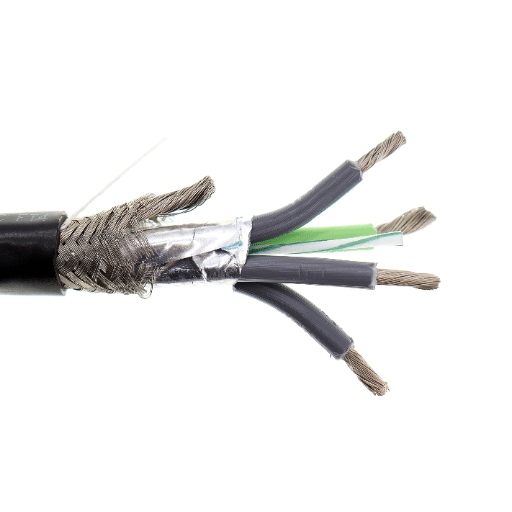
Selecting the correct Variable Frequency Drive (VFD) cable is a long technical decision-making process as to get one that will offer the best performance and at the same time be safe to operate. Firstly, the cable must be able to carry high-frequency signals and EMI (Electromagnetic Interference) that would come out of the VFD circuits. It is proposed to utilize shielded cables, and more importantly, those with copper tapes or braided shields since they produce great effects in decreasing the EMI and thus the possibility of the surrounding equipment becoming faulty.
The material of the conductors is another very important oversight. The copper conductors with a high-quality level should be considered as they show an excellent conductance and the continuous operation is not a problem for them. The conductor’s insulation should not only be able to take high voltage spikes but also have good electrical insulating and thermal conductivity properties. Insulation materials like cross-linked polyethylene (XLPE) or ethylene propylene rubber (EPR) have very good electrical properties and also their thermal conductivity gives the cables a longer life.
The way in which a cable is constructed is also a significant factor to consider, the cable’s sturdiness when being continuously stressed and bent under dynamic conditions being a primary factor. Cables that come with a higher voltage level, usually more than 1kV, suit well for most VFD installations. Besides, a strict observation of the industry standards, such as UL 1277, CSA C22.2, or IEC 60092, will increase the level of reliability and make the cable the appropriate one for the specific installations.

System is at risk of a performance down cause of no grounding as it may lead to electrical noise, equipment malfunction, and safety hazards. Be advised that the grounding is made according to the manufacturer’s guidelines and the existing standards.
For the VFD system the cables with not enough gauge and not fitted with the right voltage rating can result in overheating, energy losses and system not functioning properly. It is your obligation to confirm that the cable specs meet the VFD system requirements.
A VFD operation is in danger of experiencing electromagnetic disturbances due to inadequate or improperly terminated shielded cables. Properly shield and ground the cable termination for the sake of the effectiveness of the system.
An excessive bend radius causes the cable’s insulation or conductors to be harmed, this in return will lead to performance and safety issues. Cabling bending should be within the manufacturer’s specs all the time and not beyond.
If you don’t secure wires loosely or improperly, the issue will be mechanical stresses, and vibrations which can result in the wearing out, insulating of the wires, or the wires to disconnect. The right thing to do is to fasten the cables securely with the help of appropriate clamping or supporting devices.
One of the main issues faced by an electrician regarding the power supply system is the inappropriate termination of cables. Unprofessional and unskilled terminations, such as slipping off the insulation and not connecting to tightly, or even making the use of the incorrect tools for termination, will cause the malfunction of the system due to the fact that the system will have a poor resistance to the terminal connection. Data demonstrates that a high percentage of the issues happening with electricity in the latest technology can be directly by-passed to the termination being not proper, and that puts a lot of pressure on the counterpart to be extra careful and follow the standards to the very letter. Abiding by the cable manufacturer’s cut over points and grounding conductor point torque spec is a big leap in quality and workmanship. Moreover it pays the right way to plan ahead and consider all the materials’ and system’s coexistence issue.
Disregarding thermal issues in electrical or electronic systems could produce disastrous results such as considerable performance degradation, system instability, and early failure of the parts. One adverse effect of the conversion of electrical energy is the production of heat; very high temperature could be reached without the use of proper cooling methods which could put the components at risks that lead to breaking down of the insulation, separation of the solder joints or in the worst case even the thermal runaway in the semiconductors. A good example is a small temperature increase say 10°C which is typically above the specified range that may reduce the lifespan of a component by 50% as the Arrhenius equation, and the one used in the field of reliability engineering, illustrates.
In order to lower the threats, engineers will have to make thermal management their highest priority and one of the methods they may use is implementing proper venting, utilizing heat sinks, and selecting materials with a high thermal conductivity. The key role of Thermal Interface Materials (TIMs) in achieving effective heat transfer between components and heatsinks thus avoiding locality of high temperatures is also noticeable. Moreover, deferentially designing for optimal power distribution and thermal derating during the system design outset can greatly increase the long-term reliability. The very same tools that are used to monitor the system such as thermal imaging or temperature sensors allow for the provision of crucial real-time data collection for the purpose of running condition assessment and control.
Disregarding the necessity of electromagnetic interference (EMI) shielding can result in adverse effects on the performance of the system, and this is especially the case in places where the number of electronic devices is high. EMI shielding, on the other hand, has the function to restrict the movement of unwanted electromagnetic waves and keep them from interfering with the functioning of the components of a delicate nature. If proper protection is not provided, it will be an open invitation to signal impairment, crosstalk, and, in worst-case scenarios, no system operation at all. It is very crucial for regulatory standards to be strictly adhered to; hence, the various devices’ electromagnetic compatibility (EMC) could be ensured at all times.
Copper, aluminum, and special types of conductive materials are widely used materials for EMI shielding, providing efficient conduction and low-impedance paths to the electromagnetic waves. In the same way, having a sound grounding strategy is an issue of the same importance because ungrounded sheaths may well serve as perfect conductors for the electromagnetic waves and amplify the interference instead of reducing it.
It is suggested to carry out troubleshooting of all the shielding and grounding devices at certain intervals to avoid a situation where other components can be weakened, that is, to maintain performance integrity all the time by replacing faulty materials as soon as they are detected.
Make sure that the location of the installation is absolutely dry and clean without any traces of dust for an extended period of time and be aware of temperature fluctuations being one of the causes of degradation of materials and subsequently loss of efficiency.
One of the main practices with which EMC compliance is attained is to continually perform tests on the robustness of the system to such conditions. One of the other standard tools that are used is to determine the amount of interference in the air and the resistance of the shielding.
It is the best solution to need new components for the new products or designs. This is to reduce the effect of electromagnetic interference on presently used systems.
The performance of frequent inspections and maintenance is very much necessary for the equipment to have a long life and be perfectly operational while still meeting the electromagnetic compatibility (EMC) standards. It is to be considered that the equipment’s shielding should be maintained at its best. The physical condition of the equipment may be checked for the corrosion and damage on the shielding. The next step is to ensure bonding has not yet been compromised and to look for separation of the seams.
In the detection of any new signal leakage or susceptibility issues, diagnostic tools should be applied. Predictive maintenance as an example of a quite fresh industry idea that has been underlined as necessary to achieve data-driven monitoring that helps to prevent failures even before they can happen. Combining tools, companies can reduce the time of being without work, have more reliable systems, and comply with the regulations in a very economical way.
Choosing the right type of cable for a certain task means having a good grasp of the sectional requirements for power, environment, and mechanics. There are several points to be taken care of and the most important ones are the capacity of the cable, the voltage rating, the material for the insulation, and the effects of moisture, heat, and chemicals. Furthermore, the cable’s mechanical strength, vibration resistance, and flexing capabilities are very crucial to the industry and mobile applications, the first two cannot be especially ditched.
One of the very clear examples is the case of higher voltages where the cables with strong insulation and high dielectric strength shielding are necessary to lower the risk of their breakdown. In the same manner, in the case of varying temperatures in the environment, the cables using materials like cross-linked polyethylene (XLPE) or ethylene propylene rubber (EPR) have the advantage of being thermally stable. Shielded cables may also be required in times of a great deal of electrical noise due to different machines running at the same time which would make it to miss the electronic signals, and therefore, deteriorating the quality of data of sensitive systems.
Standards like UL, ISO, and IEC provide all-embracing rules concerning cable ratings, testing techniques, and efficiency; hence, it is mandatory to use these standards’ laws for the supply chain process, as it not only minimizes discrepancies but also secures a long period of an economically viable operating system. Last but not least, a precise estimation of the application’s power usage pattern, ambient exposure, and connectivity demands is taken into account for the most appropriate cabling proposal.
When picking the cable for the task, it is necessary to compare the cable conductor and insulation ratings to the VFD cable rated voltage and the motor power and horsepower. For keeping the voltage up and the load at the maximum, the option of stepping up might become necessary along with the selection of a bigger wire gauge or AWG accordingly. The use of proper shielding and good grounding methods not only help to lower EMI but also to provide the protection necessary for insulation breakdown at higher frequencies. The cable specification has also to be checked according to the drive and motor nameplate and the need to choose between building wire and industrial automation cables depending on the environment has to be considered.
When the correct variable frequency drive cable is selected, there will be no downtime due to power loss. Moreover, this will also help to decrease the common-mode currents and EMI which can easily destroy the motor bearings and other electronics. Having a VFD cable that is 1000V or 2000V rated when necessary, with the correct shield, also aids in preventing the life of the machine, which may otherwise be reduced. The cable, for example, not only gives the power to the system but also provides control on the noise at higher frequencies through the system. So be very cautious about the cross-sectional area and the size of the conductor for they must be such to carry the full load currents and at the same time, the voltage drop must be kept to a minimum
The nameplate of the engine is very important as we can find such crucial data mentioned as the full load amps, horsepower, and voltage that eventually will determine the size of the conductor and the insulation required. Take the nameplate full load current as a guide to select the appropriate American Wire Gauge and it may be further increased for long runs or high ambient temperatures. When the motor is large or the distance is long, the conductor of a larger gauge may be needed in order to maintain the efficiency of electrical power transmission. Further analysis of the grounding and shield requirements should be done to minimize the common-mode currents that come from the interaction of the drive and the motor.
Having proper shielding like foil shields or braided shields is a must to dominate EMI and safeguard near sensitive tools in industrial automation. By the help of symmetrical grounds, shields become easier and there is a ground wire path that goes into the motor and drive system to carry away common-mode currents continuously. To ensure the effectiveness and prevent insulation breakdown in case of higher frequencies, the shield must be correctly terminated in the drive bus. Shielded power cables are again a major factor in the quality of life of the overall equipment and a drop in downtime associated with electrical interference.