Ready to Get Your VFD Solution?
Whether you need a single drive or a complete system, we have the VFD products and engineering support to ensure your project's success.
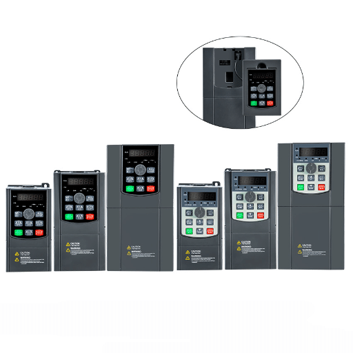
Variable Frequency Drives (VFDs) are a must in advanced industrial and HVAC systems as it has made the systems for precise control of motor speeds that results in better the system efficiency saving more energy. VFD capacitors are the principal features that make these VFDs distinctive; therefore, they are mainly responsible for the stable, safe operation and the long life duration of the device too. Knowing about the different types of VFD capacitors, choosing the correct size that fits your needs, and having the knowledge required to carry out the work of changing them on time and in the right way can all lead to a considerable improvement in the reliability of the system and the efficiency of the operation. And this document will be an ultimate guiding hand for you, opening up the world of VFD capacitors by supplying you with the doable, powerful insights, and then helping you make the right decisions that will ensure the protection of both your equipment and your money
Capacitors used in Variable Frequency Drive (VFD) are the key parts in the VFD system without which VFDs could not function as they stabilize the voltage and remove the electrical noise. They help in both the functions of storing and releasing the electrical energy which, in turn, results in balancing of the power supply and thus ensuring a constant motor operation. The main two types of capacitors that are widely employed in VFDs are the electrolytic capacitors which are meant for the energy storage and the film capacitors that are responsible for the reducing of the harmonic distortion. Their wrong selection and occasional maintenance can lead to the failure of the VFD system and also to the inefficiency of the power system, while the right selection and proper maintenance can have a positive impact on the efficiency of the power system and the life expectancy of the VFD.
The primary function of a VFD capacitor is to maintain, regulate and fix the voltage coming out of the Variable Frequency Drive. This can be done owing to their ability to very quickly charge and discharge the electrical energy while compensating for the voltage changes and removing the noise of the electrical system. Electrolytic capacitors, which are commonly used in DC bus stabilization, pay the energy they very slowly store back right when it is needed; thus, keeping the voltage level continuously the same; film capacitors, conversely, widely used in the output stage, are true. They combine this with an ability to give corrective features that eliminate the noise and distortion from the power line. These three components are critical in enabling the VFD to function at its best by giving it support for comfortable motor control, reducing the risk of overheating, and at the same time keeping the electrical signals within the realm of tolerance. The trend in capacitor technology, particularly the use of better dielectric materials and the introduction of higher thermal efficiency, only serves to drive their strength and flexibility further in highly demanding industrial environments.
Capacitors that power inverters—DC link capacitors, and filter capacitors—are the two main types of variables that are usually used for the power source. In a variable frequency drive, DC link capacitors serve the important function of stabilizing the DC voltage in the intermediate circuit, for which they absorb voltage ripples and give a constant power supply to the inverter stage. Often, these capacitors are capable of managing high ripple currents, and they are also meant to work in a very hot atmosphere, a fact that makes them very important in maintaining the reliability and efficiency of the drive system.
Filter capacitors are employed to reduce electromagnetic interference (EMI) and filter out high-frequency noise generated during the switching operations of the inverter, while the inductors are typically used to limit undesirably high ripple currents. Resonant capacitors, or passive SSLCs, are non-linear components and typically consist of two types, series and shunt capacitors. Series capacitors are used to improve the grid’s overall quality by suppressing harmonics, protecting against disturbances, and reinforcing voltage regulation in case the grid is below an acceptable level. On the other hand, shunt capacitors are found to be the most efficient, as they compensate only the real power component of the harmonic currents flowing through them, thus freeing the grid system from the burden of dealing with excessive reactive power generation.
Capacitor performance is of great importance in motor control applications, when precision and reliability are the main challenges. It is obligatory to have high-quality capacitors to realize stable DC bus voltage within Variable Frequency Drives (VFDs) and to minimize the charger causing voltage dips and leading to performance degradation and equipment failure. Innovations in capacitor materials, such as metallized film and ceramic, have significantly increased the results under energy storage and voltage capability. These developments have a direct effect on making the motor-drive systems more energy-efficient, also leading to power density reduction and increased manufacturing robustness. Besides, the thermal management technologies have improved in a way that the capacitors can still operate efficiently at an increased temperature which is especially important in the industrial environment where heavy-duty applications and harsh climatic conditions are the norm. The industry now judges modern capacitors, which not only help the motors to operate more efficiently, but also save on power and at the same time, extend the life of the overall motor control system, by passing or surpassing stringent tests of quality.
Various capacitor types are generally included in Variable Frequency Drives (VFDs) as per their specific roles and operational necessities:
The VFD manufacturers can boost performance, and boost the VFD efficiency and longevity by matching the right capacitor to the right application within the VFD.
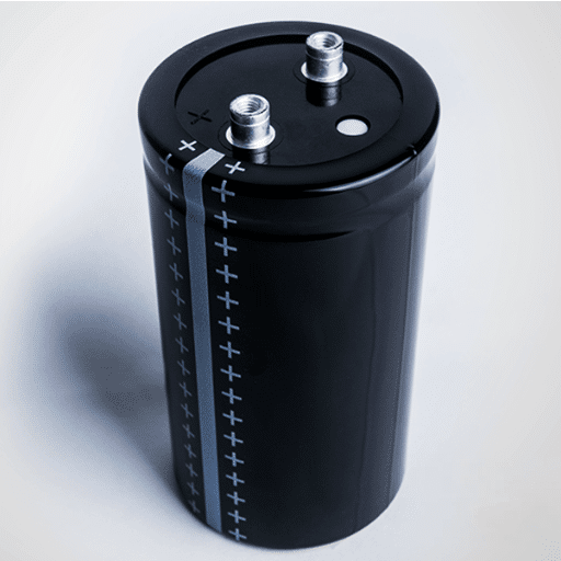
In Variable Frequency Drives (VFDs), electrolytic capacitors play a key role as one of the most important interior components as they can pack a great amount of capacitance into a confined space. They are capable of handling large amounts of electrical energy and, therefore, the continuous and uninterrupted operation of the DC link is secured. The capacitor technology of choice in VFDs is aluminum electrolytic owing to its being the most economical type available and having a large range of ampere-seconds unit, i.e., capacitive charge, along with being broadly distributed all over the world.
The most recent innovations are the result of an increase in the quality of electrolytic capacitors in terms of their temperature stability and service life, an issue that is also crucial for their use in industry. A bigger part of the present make-ups are now with Equivalent Series Resistance (ESR) values fairly reduced, which in turn led to less power loss and better system efficiency. Also, manufacturers have come up with lifetimes being longer than before even for such tough conditions as high voltages and high temperatures.
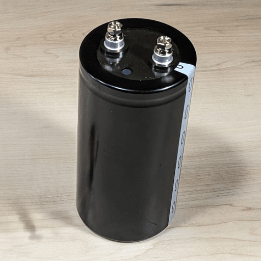
On the other hand, electrolytic capacitors have their limitations as well. The fact that they age very fast and are the most sensitive to high temperature are the main reasons for performance degradation over time. This is the main reason why electrolytic capacitors are usually blended with other types, like ceramic or film capacitors, and placed where high frequency is the main operating condition system-wise, so the whole system reliability is guaranteed. Therefore, the proper electrolytic capacitors maintenance, selection, and thermal management of are the very first steps to keep the VFDs working at their optimal performance levels as well as at long life span.
Film capacitors, often referred to as plastic film capacitors, utilize thin dielectric films and are used for storing electric charge. Because of their great performance characteristics, they are widely used in different high-frequency and high-power applications. The main advantages of these capacitors are their very low equivalent series resistance (ESR) and the fact that one can absolutely rely on their performance even when the conditions are unfavorable, and the temperature is high. Besides, they are good at coping with high ripple currents and at the same time being immune to the change in the capacitance with time which are the typical behaviors found in those systems such as variable frequency drives (VFDs), renewable energy inverters, and automotive power electronics.
The gains in capacitor technology in the film sector are hard to ignore especially with the introduction of better dielectric materials and metallization methods that result in the densification of capacitors and increase of their voltage tolerance limits. The breakthroughs are also credited for allowing the creation of more compact and at the same time totally reliable and efficient products. Film capacitors are additionally equipped with the life-saving feature of self-healing, which makes it possible for the capacitors to restore from the dielectric damages that are induced by the stress of electricity passing through and, thus, expanding their service life. The hard-to-beat operating parameters of film capacitors and their robustness in the environment place them as the go-to components for achieving the most cost-effective and energy-saving electrical networks, considering they are used in conjunction with other types of capacitors to enhance the overall performance of the circuit.
| Capacitor Type | Key Feature | Voltage Rating | Tolerance | Lifespan | Typical Use | Advantages | Disadvantages |
|---|---|---|---|---|---|---|---|
| Electrolytic | High capacitance | Low to Medium | Moderate | Short | Starting motors | Cost-effective; compact size | Short lifespan; polar installation |
| Film | Dielectric self-healing | High | Low | Long | Continuous operation | High reliability; thermal stability | Larger size; higher cost |
| Ceramic | Compact and multilayered | Low to Medium | Tight | Long | Noise suppression | Excellent for high-frequency use | Limited capacitance range |
| Mica | High precision, rugged | High | Very tight | Very long | High-frequency circuits | Extremely reliable; high accuracy | Expensive; bulky |
| Tantalum | Stable and long-lasting | Medium | Low | Long | Small motors, sensitive circuits | High stability; compact size | Sensitive to overvoltage |
| Supercapacitor | Extremely high capacitance | Low | Moderate | Moderate | Energy storage | Enables rapid charge/discharge cycles | Expensive; low voltage limits |
When it comes to selecting the right value of a capacitor, there are a number of factors that need to be taken into account:
Through a synthesis of these considerations and a systematic review of the manufacturer’s data, the best capacitor to fit the unique performance needs of the circuit of the given parameters is determined.
When choosing a capacitor for an application, the main parameters to take into account are the capacitance, voltage, and the power handling of the ripple current of the chosen capacitor. The first step is to see the capacitance that will be needed to meet the operation requirements of the circuit. This value is usually determined from operating frequency or required time constant or it may be the energy storage needed. For example, in the case of filtering applications, the formula for capacitance can be used to give an answer:
C = 1 / (2π × f × Xc)
Where:
Then, check the capacitor’s voltage rating to be significantly higher than the maximum voltage it will encounter in the application. A commonly used rule of thumb is to select a voltage rating that is at least 1.5 to 2 times the circuit’s highest voltage to make provision for a safety margin.
As an extension, the ripple current specification should also be reviewed. When working in power supply circuits or related applications, capacitors need to be able to deal with the ripple current without getting too hot. Normally, companies give capacitors’ ripple current ratings in their specification sheets and assigning these ratings to the requirements of your circuit is a must for the sake of dependability and preventing early failure.
The capacitor size can be ascertained in a very accurate manner by mixing electrical calculations with the analysis of thermal performance and the constraints of space. Utilize simulation tools or circuit models to double-check the choice and at the same time to closely follow the dynamic behavior and the instantaneous and overall performance under changing loads.
The size of the capacitor has a direct impact on both the speed and the torque of the motor since it governs the angle of the phase and the entire power going into the motor. If the capacitor of the correct size is chosen, a good phase shift will take place that will lead to efficient torque production and the motor maintaining the required speed. Capacitors that are too small in size can lack in the phasor correction needed and hence loss of the torque, ill performance of the motor, and in the end, overheating can take place due to energy inefficient conversion. The opposite of this situation could be found in the case when the capacitors are too big. Overcorrection can take place and very high inrush currents and operational instability can be among the problems.
One can perceive the necessity of mechanisms like dynamically adjusting ones if one considers the latest progress in motor control systems and capacitor design. Inclusion of such adaptable solutions assists in the process of changing the mode of operations. This, in turn, leads to the optimization of performance in the present moment. It also has an effect on the stability and energy efficiency of the operations in the system. So, wind observed that the process of adjusting the capacitor size just as per the load profile can lead to good improvements in the performance criteria, noticeably strong regulation of speed and uniformity (of torque) under the varying conditions.

Considering these factors carefully will result in the selection of the most suitable capacitor for both system performance enhancement and long-term operational efficiency.
A good examination of system requirements is the most basic part of the capacitor integration in Variable Frequency Drive (VFD) systems. The first step is to study the voltage and current profiles of the system, and then to keenly observe the peak operating conditions, any variations, and also the transient events, if any. This data will make it easier to understand the electrical stress on the capacitor. Moreover, the environmental operating temperature range needs to be investigated because high temperatures have a great effect on the lifespan and efficiency of a capacitor.
It’s equally important to know the harmonic profile of the system. The high harmonic distortion can cause thermal stress and resonance the hard way that the use of capacitors especially designed to handle these challenges would be a must if one wants to go on with the project. At last, it’s very important to evaluate the expected load cycling frequency and duration. Capacitors that are part of systems with cyclical starting and stopping or variable loads should have high mechanical and electrical stress tolerance capacity for prolonged and reliable operation. The VFD system has its operational parameters, and detailed technical data regarding these can make all the difference in identifying the right type of capacitors for the system.
The major operational conditions like voltage, current, temperature range, and frequency need to be described clearly. Besides, attention has to be drawn to the harsh conditions such as harmonic distortion levels, ripple currents, and the ambient operating temperature during Variable Frequency Drives (VFDs) operation. These conditions directly affect the type and design of the capacitor required.
Capacitors that have dielectric materials of the sort of polypropylene or ceramic generally are characterized by better thermal stability and electric operation. The material with the much-maligned Equivalent Series Resistance (ESR) can trick one into thinking that it’s further away from the operation of the electrically powered device. Plastic as a substrate material has ESR that can suppress heat generation and resist harm to the device under extreme environmental conditions.
Plan on choosing capacitors that have even bigger endurance ratings than your application is expected to require. For example, electrolytic capacitors should be able to handle high ripple currents if the operating transient line is either very noisy or keeps changing. You had better anticipate the highest peak loads, as well as providing the already needed safety factor, so that failures do not happen too soon.
Include in the calculations the outside factors like humidity, altitude, and the possible corrosion that your parts may be exposed to. Protect capacitors by adding coatings or making them in harsh environments, usually also encapsulating them around. If not, they could be destroyed quickly, making the performance unreliable and leading to early failure.
Make sure that the capacitors you intend to purchase comply with the standards of the industry IEC 60384 or AEC-Q200 for automotive applications. Besides, some natural tests can be carried out to confirm the performance under real conditions, e.g., by subjecting the capacitors to thermal cycles or exposing them to operating voltages, to the limit of their specs, dictating a thorough test.
In places that have very little space, the best thing is to go for small capacitors with high volumetric efficiency. The production of such form-factor capacitors that do not give up performance and at the same time handle even higher power densities has become possible due to technological progress.

Make sure all the power switches to the Variable Frequency Drive (VFD) are fully off and disconnect it from all power sources. Check that the system is completely de-energized by the use of a properly rated multimeter to avoid any potential electrical hazards surreptitiously.
Before handling the capacitors, dissipate all energy remaining in the device. Use a resistor-compatible discharge tool to universally bring down the voltage levels at the capacitor terminals.
The VFD casing will be removed; follow the safety protocols that are stated in the manufacturer’s guidelines. By routing through the VFD’s schematic or layout diagram, the location of the capacitor bank can be determined.
Look at the capacitors that are in place and that have readable signs of having been bad, such as they may be bulging, leaking, the casing may show burn marks, etc. Their specifications- that include capacitance, voltage rating, and polarity- need to be taken for the right replacements.
It’s recommended that insulated tools be used to disconnect the terminals and then carefully remove the damaged capacitors. Please be gentle, as the excessive application of force may harm the surrounding components or the PCB traces.
The best capacitors to use are those that have the same specifications as the original ones or that are the manufacturer’s recommended equivalents. Always remember about the polarity (when it applies), and make a good connection.
Verify each and every single way it is connected to prevent any problem later when it gets used. Weak or wrong connections can cause the equipment to malfunction or present safety risks.
Once you finish replacing the defective part, keep on setting the VFD casing up again. This has to be done so that all the protections and covers are properly placed and fastened.
Restore the VFD power gradually and watch to see the system starting up and running. Ascertain the fact that the system runs without friction, i.e., no error codes or any other performance issues.
Regular inspections and maintenance of the capacitors are expected to extend the VFD life and raise system reliability. All information concerning the replacement of a capacitor should be accurately preserved for future use.
The major step in the process of replacing the capacitor is in the preparation, so it is important to make a good start and take all precautions to be both safe and efficient. Firstly, the checking of the specifications of the replacement capacitor has to be done, so that they can match the required parameters such as the voltage rating, capacitance, and tolerance. Go to the technical documentation of the VFD and confirm compatibility and the manufacturer’s recommendations in this way.
Don’t forget to put on the proper work clothes before you start handling any of the electrical parts and you have all the tools that will be needed for the task. Some of the personal protective equipment (PPE) required can be, for example, insulating gloves, safety glasses, and a multimeter. Shut down and isolate the VFD and make sure there is no residual voltage held by the capacitors and disable power to the VFD – capacitors can hold a charge after the circuit was switched off.
Also, during the inspection process, it is crucial to check the VFD for any damaged components, burning marks, capacitors that look swollen, and corroded connections. These might be signs of problems requiring attention beyond just capacitor replacement. The findings and the state of the system should be documented so that a detailed maintenance record can be maintained.
At last, before the reassembly, make certain that the workspace does not contain any dust, litter or dampness because these can be harmful to the electronic components during the reassembly process. This careful preparation following the highest technological standards makes sure that the whole process is conducted in a right way and the lifetime of the system is prolonged.
Once the replacement of the components is finished, it is important to do all the necessary tests to check the functionality and reliability the system. One of these tests is verifying proper assembly and alignment of each component by a visual check of every connection. The status of circuit continuity can be tracked by the use of a multimeter, that also gives a negative result. Another point to check for is any overvoltage on the circuit that can be verified by the specified tolerances given in the datasheet.
Capacitor reforming is the process of reconditioning the electrolytic capacitors by increasing the system’s voltage slowly till it matches the working point. This practice is crucial especially if the capacitors have been left unused for a long time. It is highly recommended to use a variable power supply that will gradually increase the applied voltage along with the monitoring of the current draw. An abnormally high current that flows can be a sign of a problem or an improper reforming process. Before reaching the rated voltage, some time should be given for the capacitors to stabilize at each voltage increment. For the purpose of traceability and future reference, make a maintenance log recording all the voltage applied, current readings, and stabilization times.
In the end, carry out the testing with peak operating performance conditions. It should also entail putting the system under load to guarantee that the newly installed parts are in perfect working condition, and also to detect any overheating or instability issues. The correct performance of the post-replacement testing together with the capacitor reforming is not only going to make the system operable right away, but will also lay the foundation of the system’s robust durability and efficiency.