Ready to Get Your VFD Solution?
Whether you need a single drive or a complete system, we have the VFD products and engineering support to ensure your project's success.

VFD bearing current damage is what happens when a voltage builds on the motor shaft and discharges through the bearings. The drive’s fast switching creates that voltage, the bearing grease film acts as a switch, and the discharge pits the raceway a few microns at a time. It is an electrical failure that looks mechanical from the outside.
Nadia ran maintenance at a paper mill near Trondheim, and for eleven months she had a fan motor that ate bearings. Four replacements, same location, same frosting on the raceway each time. The electricians checked alignment, balance and lubrication, found nothing, and fitted another bearing.
The fifth replacement was going in when someone asked a different question. Not “why did the bearing fail,” but “what keeps failing it.”
That question is the one this guide answers. It shows you how to tell electrical damage from mechanical damage before you buy anything, and how to match the fix to the current that is actually flowing. For the wider picture of what a drive does and doesn’t do to a motor, see our VFD motor life guide.
Key Takeaways
- VFD bearing current damage is electrical, not mechanical, and the raceway shows it: fluting forms while the machine runs, with shiny, evenly spaced grooves closer together than the ball spacing.
- A standard multimeter cannot measure shaft voltage accurately on a drive output. It reads a low number and gives false comfort. Use an oscilloscope with adequate bandwidth.
- Two different currents cause the damage, and they need different fixes. A shaft grounding ring discharges capacitive current; an insulated bearing interrupts circulating current.
- Insulating one bearing without providing a discharge path moves the problem to the other bearing. ABB’s own guidance says the unprotected bearing can then fail twice as quickly.
- Damage appears within a few months on unprotected motors, against an expected service life of five years or more.
Start here, before you buy a part. The two failure modes leave different marks, and both marks are readable.
Electrical fluting produces evenly spaced parallel grooves across the raceway, sometimes called a washboard pattern. Two details separate it from mechanical wear.
The grooves sit closer together than the rolling element spacing, because an arc cuts them rather than the balls. And the groove bottoms look shiny or melted, because each discharge is a tiny arc that briefly melts the steel. There is no corrosion tint.
False brinelling is the usual misdiagnosis. It forms when the machine is stopped, from vibration or during transport, as the rolling elements fret against a stationary race. Its grooves sit at exactly the rolling element spacing, and the bottoms are dull, with reddish-brown fretting corrosion. That reddish tint is iron oxide, and it is the simplest visual discriminator: bright and melted means electrical, dull and rusty means mechanical.
You do not have to dismantle the motor to suspect electrical damage, and most guides leave this part out.
Early electrical erosion does not follow the classical bearing defect frequencies. A bearing analyser looking for BPFO or BPFI finds no match and may call the bearing healthy. Instead, the damage shows as elevated high-frequency energy, a broad “haystack” band around 2-4 kHz with no mechanical fault frequency to match.
High energy without a matching mechanical signature points at an electrical origin. That mismatch is the finding, not the absence of one. Once fluting is established, the classical bearing frequencies do appear, along with sidebands from the rhythmic grooved surface. By then the damage is done.
Two more field checks cost nothing. A damaged bearing often produces a high-pitched whine that tracks speed, rather than the low-frequency rumble of mechanical spalling. And if you open the housing, blackened or carbonised grease confirms that current has passed through it.
Seeing repeated failures on one motor and suspecting current? Send us the drive model, the motor frame and the cable length, and we will tell you which current type to expect. Talk to our engineering team before the next bearing goes in.
The mechanism has three stages, and knowing them explains why the fixes look unrelated to each other.
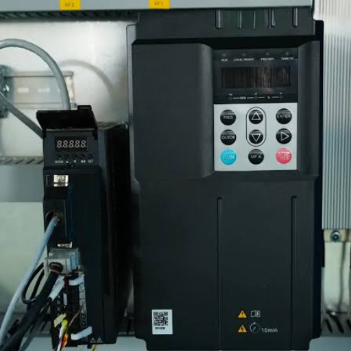
A VFD doesn’t output a smooth sine wave. It switches DC at high frequency, typically several kilohertz, to synthesise one. The three outputs do not sum to zero at every instant, so a common-mode voltage appears between the motor windings and ground.
That voltage doesn’t need a wire to reach the shaft. The stator winding and the rotor are separated by the air gap, and two conductors separated by an insulator form a capacitor. The common-mode voltage couples capacitively across the air gap onto the rotor, and the shaft voltage rises.
Measured shaft-to-ground pulses on drive-fed motors reach 20 V to 25 V. The discharges last only nanoseconds, which matters enormously for how you measure them.
The bearing doesn’t conduct continuously. Its rolling elements ride on a film of grease or oil that is, while intact, an insulator. Shaft voltage builds freely until it exceeds the dielectric strength of that film, and then it discharges through the bearing in a single arc.
The film is the switch, and the switch is not stable. Its breakdown voltage depends on film thickness, which depends on load, speed and temperature.
Higher speed thickens the film and raises the threshold. Higher load compresses it and lowers the threshold. This is why a heavily loaded motor at moderate speed can be more vulnerable than a lightly loaded one at high speed.
Two distinct currents damage bearings, and they behave differently.
| Current type | What drives it | Where it usually appears | What it attacks |
|---|---|---|---|
| Capacitive discharge (EDM) | Common-mode voltage coupling across the air gap | Any frame size, but most reported below roughly 55 kW | Whichever bearing offers the easiest path to ground |
| Circulating (shaft) current | High-frequency flux linking the shaft, stator and frame | Larger frames, reported from roughly IEC 280 / NEMA 440 upward | Loops through both bearings and the frame at once |
The power range where each dominates is not a clean line. Sources place the crossover anywhere from about 55 kW to about 100 kW, and ABB notes the two can coexist in a transition band rather than swapping cleanly. Treat any single threshold as a starting point, not a rule. Frame size, cable length and how the motor is earthed all move it.
The distinction matters because the fixes are not interchangeable. This is where most partial guides go wrong.
There is no universal answer, because the threshold is the grease film, and the film is dynamic. What you can do is compare against detection limits that flag a motor worth investigating.
| Measurement | Flagged as potentially damaging |
|---|---|
| Shaft-to-frame voltage, ball or roller bearings | Above 100 mV AC |
| Shaft-to-frame voltage, sleeve bearings | Above 200 mV AC |
| Shaft voltage end-to-end (per NEMA MG1) | Above 300 mV AC |
| Circulating bearing current | 3 A to 20 A |
| Current density in the bearing | Above roughly 1 A/mm²; below about 0.4 A/mm² is broadly benign |
These come from EASA’s shaft and bearing current guidance and are thresholds for investigation, not trip points. A reading above them means measure further, not replace a part.
Here is the mistake that wastes the most time.
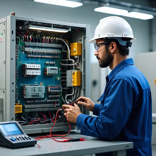
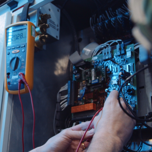
The discharges last nanoseconds and repeat at the drive’s switching frequency. A standard digital multimeter can’t resolve them. Its sampling and bandwidth are far too low, so it averages the events into a number that looks harmless.
A motor with genuinely damaging shaft voltage can read a few millivolts AC on a handheld meter and still flute its bearings within months. The instrument is not faulty. It simply cannot see the events that matter.
Use an oscilloscope with sufficient bandwidth, coupled through a shaft-riding brush or probe, and look at the waveform rather than a single number. A Rogowski coil does the same job for shaft current. Where this measurement isn’t available in-house, it’s worth commissioning from a specialist, because a false all-clear is worse than no measurement.
The organising idea is simple. Circulating current is a loop and must be broken. Capacitive discharge is a voltage and needs somewhere to go. Fitting the right fix for the wrong current achieves nothing.
That also reconciles two recommendations that look contradictory when you meet them side by side: one from ABB, one from the shaft-grounding industry. They are not rivals, because they describe two different jobs.
| Fix | Job it does | Best suited to |
|---|---|---|
| Shaft grounding ring or brush | Provides a low-impedance path to earth, so shaft voltage discharges through the ring instead of the bearing | Capacitive discharge, all frame sizes |
| Insulated or hybrid bearing | Breaks the circuit, so circulating current can’t complete its loop through the bearing | Circulating current, larger frames |
| Both together | Grounds one end and insulates the other | Where both current types are present, commonly larger motors |
| Symmetric shielded cable with 360-degree termination, plus output filters | Reduces the common-mode voltage at source, so less current exists to manage | Every installation, as the first line of defence |
This is the error that turns a fix into a new failure.
If you insulate one bearing and provide no discharge path, the current doesn’t disappear. It concentrates on the bearing that is still conducting. ABB’s guidance states it directly: with only one bearing insulated, the unprotected bearing can fail twice as quickly as it did before. EASA puts the same point another way, that when the path to the bearings is simply blocked by insulation, the damaging current seeks another path to ground.
Felix found that at a water treatment works in Antwerp. His team fitted an insulated bearing at the non-drive end to stop a recurring failure, and the failures stopped at that end. Then the drive-end bearing began failing instead, more often than the original had.
Nothing was defective and nothing was installed backwards. The insulation had done exactly what it does: broken the loop for one bearing and redirected the discharge to the other. That motor needed a grounding ring at the drive end and insulation at the non-drive end. Each current type then had a barrier of the right kind.
Two further cautions follow from the same principle.
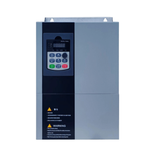
Specifying protection for a new installation is cheaper than diagnosing it later. Our engineers can match the bearing protection to your frame, cable and earthing arrangement before the motor arrives. Explore our VFD product range or send us the drive and motor details.
The bearing is not always the only victim, and this is where a bearing-focused diagnosis can miss the real scope.
Damage can extend into the driven equipment. Coupled machinery, and gearbox bearings in particular, can carry the same circulating current. The wider compatibility issues between a motor and its drive are covered in our guide to motor compatibility with VFDs.
Kofi saw it at a gold mine in Ghana: the motor bearings had been protected for two years, yet a gearbox bearing kept failing. The shaft was conductively coupled to the gearbox, so the current routed around the protected motor bearings and into the driven train. An insulating coupling between motor and gearbox fixed it.
Three installation choices lower the current at source, before it needs managing at the motor:
Filters reduce shaft voltage but don’t eliminate it, and they address the capacitive mechanism more than the circulating one. Treat them as reducing the problem, not removing it.
The pattern behind almost every expensive case is the same: a part is replaced repeatedly, and the current path is never examined.
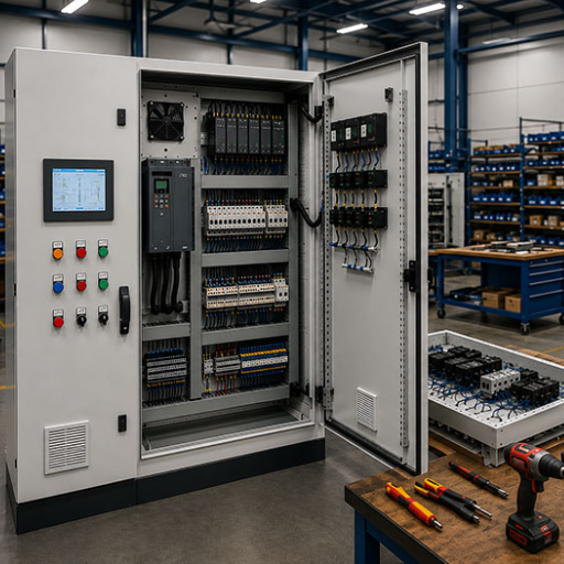
Specify protection when the drive is specified, not after the third bearing failure. The decision inputs are the frame size, the cable length and construction, the earthing arrangement, and whether the driven equipment is conductively coupled. Ignore them and a bearing designed for years can fail in months.
A short checklist, in the order that saves the most time:
The most common reason is an unmanaged current path. A drive-fed motor develops shaft voltage from common-mode voltage, and it discharges through the bearings unless a ground path carries it away. Repeated failures at the same location, with the same raceway frosting, point to a current problem rather than a mechanical one.
It depends on which current is present. Capacitive discharge is handled by a grounding ring, which gives the shaft voltage somewhere to go. Circulating current is handled by an insulated or hybrid bearing, which breaks the loop. Where both are present, common on larger motors, you need both: the ring at one end, the insulation at the other.
There is no single figure, because the limit is the grease film’s breakdown voltage, which varies with load, speed and temperature. For investigation purposes, EASA flags shaft-to-frame readings above 100 mV AC on ball or roller bearings, and NEMA MG1 references 300 mV AC end-to-end. Above those levels, measure with proper instrumentation before acting.
No, not usefully. The discharge events last nanoseconds, and a standard multimeter’s bandwidth is far too low to capture them. It will report a low, reassuring number on a motor that is actively damaging its bearings. Use an oscilloscope with adequate bandwidth, or have a specialist take the measurement.
Not inevitably, and not through the motor’s own fault. A drive creates the conditions for bearing current, and whether damage follows depends on the frame size, the cable, the earthing and whether protection is fitted. Plenty of drive-fed motors run for years without damage. The failures cluster where those installation factors are left unmanaged.
Yes, in specific circumstances. A coated insulated bearing forms a capacitor across itself, and high-frequency circulating current can charge it and arc through the rolling elements. Where an insulated bearing fails electrically, the fix is usually a hybrid or ceramic-rolling-element bearing rather than additional insulation.
VFD bearing current damage is an electrical fault wearing a mechanical disguise. The drive creates a common-mode voltage, the air gap couples it to the shaft, and the grease film decides when it discharges. Three things follow from that, and they are the whole of the article in miniature.
Read the raceway first, because bright and melted means electrical and dull and rusty means mechanical. Measure shaft voltage with an oscilloscope, because a multimeter will tell you what you want to hear. And match the fix to the current: a grounding ring for discharge, insulation for circulating current, and never one without the other where the frame needs both.
None of that is expensive at the specification stage. All of it is expensive after the third bearing.
If you want a second opinion on a machine that keeps failing, contact our engineering team with the motor frame, the drive model, the cable length and a photo of the failed raceway. Those four things usually settle which mechanism you are dealing with.