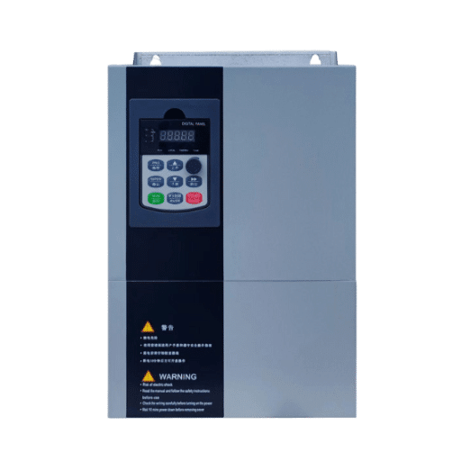
Ready to Get Your VFD Solution?
Whether you need a single drive or a complete system, we have the VFD products and engineering support to ensure your project's success.

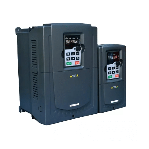
In industrial automation, the VFD (variable frequency drive) is the execution layer for motor control: it takes commands from PLCs, sensors, and supervisory systems and turns them into precise motor speed and torque. Industrial automation with VFD technology is usually the fastest-payback first step toward a smarter plant, because motors are where the energy and the moving parts are.
Electric motors consume roughly 45% of the world’s industrial electricity. Most of them still run at one fixed speed, controlled by nothing smarter than a contactor. The gap between that reality and a “smart factory” is smaller than it looks, and it starts with the drive.
You have probably sat through Industry 4.0 presentations that made automation sound like a seven-figure transformation program. This guide takes the practical route: where VFDs actually sit in the automation stack, how PLC integration works, how to pick a communication protocol, and a three-phase roadmap you can start with a single motor.
Key Takeaways
- The VFD is the automation layer that physically executes motor control: speed, torque, acceleration, and protection.
- You don’t always need a PLC. Modern drives with onboard PID and logic functions can automate a pump or fan loop on their own.
- Protocol choice follows your installed base: Modbus RTU for simple and legacy systems, PROFINET or EtherNet/IP for plant-standard integration, EtherCAT for motion-class performance.
- A phased roadmap (standalone drives → PLC integration → data and predictive maintenance) spreads cost and delivers payback at every stage.
- Most integration failures come from three avoidable causes: EMI and grounding errors, parameter misconfiguration, and protocol mismatch.

The role of a VFD in industrial automation is to execute motor control decisions. Sensors and PLCs decide what should happen; the VFD makes the motor do it by adjusting the frequency and voltage of the power it supplies. This gives automated systems precise control over speed, torque, acceleration, and stopping, plus built-in motor protection and energy data.
Without a drive, an automated system can only switch a motor on or off. With one, the system gains a continuously adjustable actuator that also reports back what the motor is doing.
Industrial automation is organized in layers, and the VFD sits at the bottom where electricity meets motion:
The VFD is the boundary device between levels 1 and 2. It takes orders from above, acts on the motor below, and reports current, torque, temperature, and fault data back up. As Processing Magazine notes in its overview of modern drives, this dual role as actuator and data source is what makes VFDs central to contemporary industrial systems.

Of everything you could automate first, motor control offers the best combination of cost, speed, and measurable return. Three cases drive that conclusion.
Motor-driven systems account for about 45% of global industrial electricity use. On variable-torque loads like fans and pumps, matching speed to demand cuts energy 20 to 50%, and facility case studies consistently report payback in under two years. No other automation investment pays back that fast, that predictably.
Fixed-speed motors force processes to adapt to the machine. Valves throttle, dampers close, clutches slip. A VFD lets the machine adapt to the process: line speeds synchronize, batch consistency improves, and product quality stops depending on mechanical workarounds.
Consider a bottling line where the filler runs at a fixed rate but upstream supply fluctuates. With fixed-speed conveyors, operators absorb the mismatch by hand, stopping and jogging sections of the line all shift. With drives networked to line sensors, each section speeds up or slows down automatically to keep product flowing evenly. Fewer jams, fewer broken bottles, less operator intervention.
Every modern drive is also a sensor package. It continuously measures motor current, torque, output frequency, heat sink temperature, and running hours. Connect that data upward, and you have condition monitoring on every motor in the plant without buying a single additional sensor. This is the quiet on-ramp to predictive maintenance.
Planning a first automation step? Our low voltage VFD systems cover motors from fractional loads up to 1,000 kW, with the protocol support discussed below. The roadmap section shows how plants typically phase the investment.
The classic automation loop runs like this: a sensor measures the process (pressure, flow, level, temperature), the PLC compares the reading to a setpoint and computes a response, and the VFD executes that response on the motor. The motor’s effect on the process feeds back to the sensor, and the loop repeats continuously.
A chilled water pump is the textbook example. A pressure sensor reads the loop, the PLC’s PID logic decides the pump should slow down, and the VFD reduces motor frequency until pressure returns to setpoint. No operator touches anything.
There are two ways to connect a PLC to a VFD, and both remain legitimate:
A practical rule: hardwire the safety-critical signals (emergency stop, run enable), and put everything else on the network.
Here is what most Industry 4.0 content won’t tell you: for many applications, you don’t need a PLC at all. Modern drives include onboard PID controllers, multi-speed presets, timers, and programmable logic functions. A booster pump set holding pressure, a ventilation fan following a thermostat, a mixer with three speed recipes: the drive handles all of these standalone.
When Amara, an engineer at a water treatment cooperative in Kenya, was quoted a full PLC panel for a two-pump pressure-boosting station in 2025, the number didn’t fit the budget. Instead, her team used the drives’ built-in PID with an alternating duty/standby program. Total control hardware cost fell by about 60%, commissioning took two days instead of two weeks, and the station has held pressure within 0.1 bar since. The PLC would have been the “proper” solution. The drives were the right one.

Protocols are where integration projects stall, usually because someone bought drives before checking the plant’s network. The main options:
| Protocol | Best For | Speed | Complexity |
|---|---|---|---|
| Modbus RTU | Simple systems, legacy plants, small budgets | Slow (serial) | Low |
| Modbus TCP | Same as above, on Ethernet | Medium | Low |
| PROFINET | Siemens-centered plants, deterministic control | Fast | Medium |
| EtherNet/IP | Rockwell/Allen-Bradley environments | Fast | Medium |
| EtherCAT | Motion control, high-speed synchronization | Very fast | Higher |
| Profibus DP | Existing Siemens legacy installations | Medium | Medium |
Work through four questions. First, what’s already installed? Matching the plant’s existing PLC ecosystem beats any technical argument. Second, how fast does the loop need to be? Process control (pumps, fans, mixers) tolerates seconds; synchronized motion needs milliseconds. Third, who will maintain it? A protocol your team can’t troubleshoot is a liability. Fourth, where is the plant heading? If cloud dashboards are on the roadmap, favor Ethernet-based protocols that bridge upward easily.
Plants that succeed at automation share one habit: they phase it. Here is the progression that works.
Start with the motors that cost the most to run badly: the big fans and pumps, the machine that fails most often. Install drives, set up soft starting and basic speed control, and let the energy and maintenance savings fund the next phase. This phase needs no network, no PLC, and no programming beyond drive parameters. Typical payback: 12 to 24 months per drive.
How do you pick the first candidates? Pull twelve months of maintenance logs and utility data. Motors that run long hours at partial load, fail repeatedly, or drive throttled processes go to the top of the list. A plant with fifty motors rarely needs more than five or six drives to capture most of the available savings in Phase 1.
Connect the drives to your control system over a fieldbus or Ethernet network. Now the process runs closed-loop: setpoints come from the process, not from an operator’s thumbwheel. Central monitoring begins, and alarms reach maintenance before failures do. This is also when application-level tuning starts to matter, because coordinated conveyors, pumps, and fans behave as one system rather than a collection of motors.
Stream drive data (current signatures, temperature trends, fault histories) into dashboards or cloud analytics. Bearing wear, unbalance, and fouling all leave electrical fingerprints weeks before failure. Facilities running condition-based programs report downtime reductions around 30%, and one documented PLC-VFD integration study in textile manufacturing measured a 30% power reduction after optimization.
Miguel, a plant manager at a packaging facility in Mexico, ran exactly this playbook over two years. Phase 1 was six drives on the worst offenders: two compressors, three fans, one conveyor. The energy savings funded Phase 2’s PLC integration across the line. Phase 3 caught a failing gearbox on the main case packer three weeks before its bearing would have seized, during the December peak, when an unplanned stop would have cost more than the entire program.

Most VFD integration problems trace back to four avoidable causes:
The VFD is the execution layer for motor control. It converts commands from PLCs and sensors into precise motor speed, torque, and ramp behavior, while providing motor protection and reporting operating data back to supervisory systems.
Not always. Modern VFDs include onboard PID controllers, multi-speed presets, and programmable logic that can automate single-loop applications like pressure boosting or ventilation control without any PLC. You need a PLC when multiple motors must coordinate or when sequencing logic gets complex.
Match your installed base first: Modbus RTU for simple or legacy systems, PROFINET for Siemens plants, EtherNet/IP for Rockwell environments, and EtherCAT for high-speed motion. Consider loop speed requirements and your team’s troubleshooting familiarity.
On variable-torque loads (fans, pumps), typically 20 to 50%. On constant-torque loads like conveyors, 10 to 30%. Well-documented payback periods run 12 to 24 months for most applications.
Usually, yes. Most three-phase motors accept VFD control, though motors built before 2000 may need output filters or shaft grounding protection. Adding drives to existing motors is the most common starting point for automation retrofits.
Industrial automation with VFD technology works because it starts where the physics is cheapest to improve. Motors consume nearly half of industrial electricity, most run uncontrolled, and the device that fixes that also happens to be a sensor, a protector, and a network node.
The path is proven: standalone drives first, PLC integration second, data and predictive maintenance third. Each phase pays for itself and funds the next. The plants that fail at automation are the ones that try to buy the destination instead of building the road.
If you’re mapping this roadmap onto your own facility, the Shandong Electric engineering team can help at any phase, from sizing a first standalone drive to specifying networked VFDs with Modbus and fieldbus support for full-line integration. Talk to our engineers about where your plant is today, and we’ll help you plan the next step.