Ready to Get Your VFD Solution?
Whether you need a single drive or a complete system, we have the VFD products and engineering support to ensure your project's success.

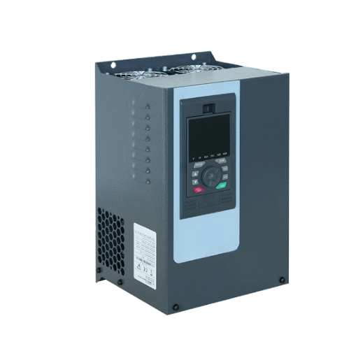
VFD overvoltage on deceleration happens because the motor becomes a generator while the load keeps it turning. The drive’s rectifier only lets power flow one way, so that returning energy has nowhere to go. It charges the DC bus until the drive trips to protect itself. The fix is to give the energy a path, or to stop generating it so quickly.
Daniel found that out on a decline conveyor at an aggregates quarry outside Pietermaritzburg. The belt ran fine loaded uphill for two years.
When the plant added a second discharge point, the drive started tripping on overvoltage at the end of every shift. His team replaced the braking resistor within a week. The trips continued.
The resistor was never the problem. The controller that should have handed braking duty to the resistor was still holding onto it. Nobody had told them the two settings compete.
This guide covers the deceleration case specifically. It shows you how to tell a regeneration trip from a supply or hardware trip, the three ways to give the energy a path, and the parameter interaction that leaves perfectly good braking hardware sitting idle. For the full fault map across all four trip timings, see our VFD overvoltage fault guide.
If your drive is tripping and you need to identify the cause before the next shift, talk to our engineering team with the trip timing and the DC bus reading. We can usually narrow it down from those two numbers.
Key Takeaways
- VFD overvoltage on deceleration is regenerated energy with no path back to the supply, so the DC bus climbs until the drive trips.
- Lengthening the deceleration ramp is the only fix that costs nothing, and it works whenever the process can tolerate a slower stop.
- Overvoltage control and stall prevention do not prevent regeneration. They work by extending your deceleration time, so the stop you get is slower than the stop you programmed.
- On several major brands, fitting a braking resistor requires disabling the overvoltage controller. Leave it enabled and the chopper may never operate.
- Above roughly 20% braking duty, a common DC bus or a regenerative drive usually beats a larger resistor bank.
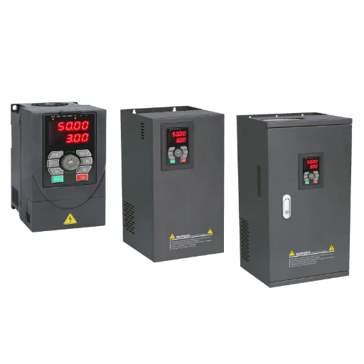
During acceleration, the drive pushes energy into the motor. If the ramp is too aggressive, the current rises and the drive trips on an overcurrent fault.
Deceleration runs the same relationship backwards. The drive lowers the output frequency, so the rotating field turns slower than the rotor. The motor crosses into the fourth quadrant and behaves as a generator. The load’s kinetic energy converts to electrical energy and flows back into the DC bus.
A standard VFD cannot send that energy back to the grid. Its input stage is a diode bridge, and a diode bridge is a one-way street. Power comes in from the supply and cannot flow back out. So the returning energy has only one place to go: the DC bus capacitors.
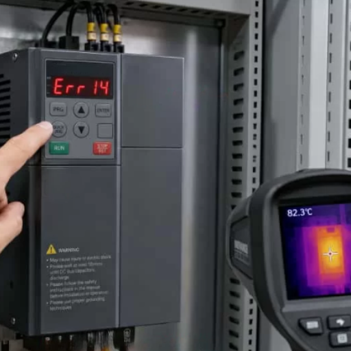
The bus voltage rises. When it crosses the drive’s protection threshold, the drive trips. That is the point where regeneration becomes a VFD overvoltage on deceleration fault code.
Typical trip levels are around 410 VDC on a 230 V class drive and roughly 770 to 850 VDC on a 400 or 480 V class drive. Confirm the exact figure for your model in the manual, because it varies.
If you can lengthen the ramp, do that first. It is free, and it is covered in detail in our VFD ramp settings guide.
Regeneration happens because the drive is trying to slow the load faster than the load’s own losses can absorb. Give it more time and the problem often disappears.
Before you quote any hardware, ask whether the process actually requires the stop time you programmed. A centrifugal pump that coasts to rest over fifteen seconds needs no braking hardware at all. A cooling tower fan that takes forty seconds to coast needs nothing either, as long as the process can tolerate it.
Double or triple the deceleration time and watch the DC bus during a stop. If the trip disappears, you have your answer, and you have spent nothing.
This is the step most often skipped, because a short ramp feels like a requirement when it is usually a default. A factory default of one second is a number designed for a demo motor with no load. It rarely suits real machinery.
There are two cases where lengthening the ramp will not clear the fault, and knowing them saves a lot of wasted tuning.
The first is an overhauling load. A descending conveyor, a lowering hoist, or an unloader drives the motor regardless of what the ramp commands. Here the energy is coming from gravity, not from inertia, and no ramp length changes that. If the overvoltage follows a mechanical state rather than a stop command, this is where to look.
The second is a stop time the plant cannot accept. If the machine has a cycle time, a positioning requirement, or a mechanical brake that has to close at a known moment, then a longer ramp is not available to you, whatever the DC bus prefers. That takes you to the next section.
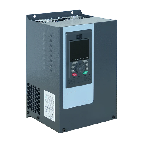
Most drives have a function that stops the drive from tripping without any additional hardware. It is called overvoltage control, overvoltage stall prevention, or a regen-stall setting, depending on the brand.
It is genuinely useful, and it is also widely misunderstood. It does not prevent the motor from regenerating. It manages the consequence.
Yaskawa states the behaviour plainly for the parameter L3-04Stall Prevention during Decel: “The Decel Stall Prevention function will increase the deceleration time to stop and the deceleration time will be longer than the setting.” On setting 1, the drive decelerates on your ramp until the bus reaches the stall level, pauses deceleration, and resumes once the voltage falls back.
That has a consequence worth stating clearly. The stop you get is not the stop you programmed. It is longer, and it is not repeatable, because it depends on how much energy the load happened to return on that particular stop.
Yaskawa goes further than most and excludes a whole application class. The same parameter page notes that the function “is not applicable for conveyor applications because the precision of the stop position is very important.”
Aisha ran into this on a carton packaging line in Sharjah. The line used a photo-eye to stop each carton at the sealing station, and the drive had stall prevention left at its default.
On light loads the cartons landed correctly. On a full pallet’s worth of product, the stop stretched by nearly a second and the cartons overran the seal head.
Nothing was faulty. The controller was simply doing exactly what it was designed to do, and the machine wasn’t built for it.
If stop position, stop time, or a mechanical brake hand-off matters on your machine, this function is a diagnostic aid, not a production setting. Where the process needs a defined stop, the answer is braking hardware, not a controller that stretches the ramp.
Ready to specify braking hardware properly? Our engineers can size the path against your real duty cycle rather than a nameplate figure. Explore our VFD product range or send us the load profile.
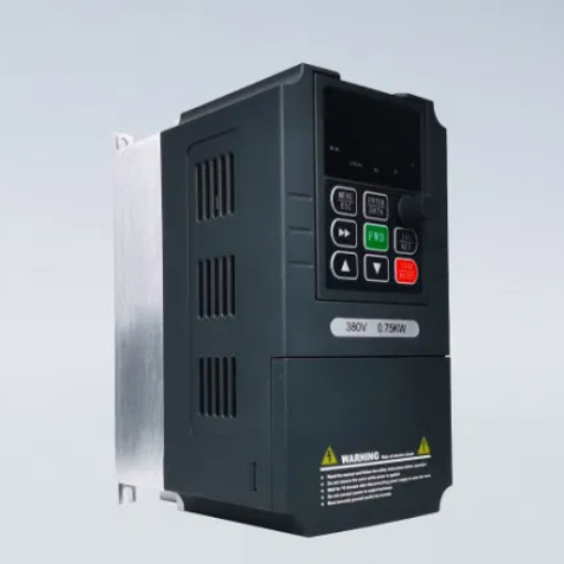
This is the part that costs people the most time, and it appears in very few guides.
When you fit a braking resistor or chopper, it takes over the job of absorbing regenerated energy. The overvoltage controller, if left enabled, is still trying to do the same job by stretching the ramp. The two do not cooperate. On several major brands, the manual requires you to turn the controller off so the chopper can work.
The patterns we checked are consistent, even though the parameter names are not.
| Brand | Parameter | What the manual requires with a braking resistor |
|---|---|---|
| Yaskawa | L3-04 |
Set to 0 or 3. With values 1, 2, 4 and 5, “the dynamic braking option will not function” |
| ABB | 2005 OVERVOLT CTRL |
Must be set to 0. The manual warns that with a chopper or resistor connected, “this parameter value must be set to 0 to ensure proper operation of the chopper” |
| Siemens | p1240 Vdc controller |
The Vdc_max control should be disabled when a braking resistor is on the DC link. Some families, such as the G120XA with p0219 > 0, deactivate it automatically |
Two things follow from this. The patterns above come from the manufacturers’ own parameter documentation, including the ABB drive manuals and the Siemens SINAMICS Vdc controller documentation.
Check the manual, do not assume. The behaviour is brand-specific and sometimes family-specific. Siemens auto-deactivates on some drives and expects you to do it on others. Assuming is how a working resistor gets diagnosed as faulty.
Measure before you replace. If a braking resistor measures correctly at its nameplate value and the bus still spikes on every stop, the resistor is probably not your fault. The chopper is not being allowed to fire. Confirm the controller setting and the chopper command before you order a part.
This is the trap Daniel fell into on the quarry belt. The replacement resistor behaved exactly like the original, because neither was ever switched into circuit.
Once you accept that a longer ramp is not available, you have three practical paths. The right one depends mainly on how often the load brakes.
| Braking duty | Recommended path | Reason |
|---|---|---|
| Under about 10% | Resistor, or a longer ramp | Heat has time to dissipate between stops |
| 10% to 20% | Resistor with external hardware | An internal chopper is typically limited to around 10% duty |
| 20% to 50% | Common DC bus, or a sized resistor bank | Sharing energy beats dissipating it, where a motoring load exists |
| Above 50%, or continuous | Regenerative drive | The resistor bank grows faster than the problem |
Duty cycle is the variable that decides most of these cases, and it is usually described in prose when it should be a number. Horizontal motion typically lands between 10% and 15%. Vertical motion is far higher, because a hoist lowering a load may regenerate for the whole descent, making 50% to 100% normal.
For the full comparison, including payback arithmetic and the constraints on grid-tied regeneration, see our guide to regenerative drives versus braking resistors. If you are still tuning the ramp itself before adding hardware, the VFD parameter settings guide covers the commissioning sequence.
One caution on braking hardware and hoists. If the load can fall, the braking path has to work when the supply does not. A resistor or a regenerative front end cannot hold a suspended load after a power failure, and a mechanical brake that is not rated to hold the load is not a substitute. Where somebody can be under the load, this belongs in the risk assessment, not in the tuning notes.
Work through these in order. The first two cost nothing and resolve most cases.
The motor becomes a generator while the load inertia keeps it turning, so energy flows back into the DC bus faster than the drive can absorb it. Because it only happens at a stop, VFD overvoltage on deceleration points at the ramp time, the braking path, or an overhauling load rather than at the supply.
Usually yes, and it should be your first test. The limits are process-based rather than electrical. If the machine has a cycle time or a positioning requirement, a longer ramp may not be acceptable, in which case you need a braking path.
Most often because the overvoltage controller is still enabled and is preventing the chopper from operating. On Yaskawa drives, L3-04 must be set to 0 or 3. On ABB drives, 2005 OVERVOLT CTRL must be set to 0. If the resistor measures correctly and the trip continues, check the controller setting before replacing the resistor.
For an occasional stop where the exact stop time does not matter, often yes. Bear in mind that it works by extending the deceleration time, so the drive will not stop as fast as the programmed ramp. For conveyors and positioning moves, manufacturers advise against relying on it.
High inertia is the usual answer. A large fan or a flywheel-coupled load stores a lot of kinetic energy, and even a modest deceleration rate has to move that energy somewhere. A long ramp or a correctly sized resistor is normally enough.
Braking duty cycle decides it in most cases. Below about 20%, a resistor is normally the practical answer. Above 50%, or where the heat load cannot be tolerated, a regenerative drive usually wins.
VFD overvoltage on deceleration is an energy path problem before it is a parts problem. The motor regenerates, the diode bridge will not take the energy back, and the DC bus rises until something absorbs it or the drive trips.
Start with the two free checks. Confirm the trip really is tied to deceleration, then extend the ramp and see whether the fault clears. Tomás cleared a tripping pump station in Valparaíso that way, with nothing more than a deceleration time change from three seconds to eighteen, and no hardware purchased at all.
When the ramp cannot be extended, choose a path deliberately. Size the braking duty first, then pick a resistor, a common DC bus, or a regenerative drive to match it. And whichever you choose, confirm how your drive expects the overvoltage controller to be configured alongside it, because that single setting decides whether the hardware you bought ever operates.
If you want a second opinion on the load profile, or help matching a braking path to a drive, contact our engineering team. We work through selection, configuration and commissioning, and we will tell you when the answer is a five-minute parameter change rather than a new cabinet.