Ready to Get Your VFD Solution?
Whether you need a single drive or a complete system, we have the VFD products and engineering support to ensure your project's success.

To make sure that motor systems work efficiently and reliably, understanding VFD (Variable Frequency Drive) control wiring is of utmost importance. Specifically concentrating on terminal connections and diagrams, this article is a complete VFD control wiring guide. Even if you are a newbie in the electrical field, this guide shall take away all the mystery from VFD terminals, and the difficulty in understanding their functions as well as their role in the broader system. By studying and thoroughly explaining the different terminal setups through practical wiring diagrams, this manual shall teach you how to diagnose and troubleshoot effectively, and thus, enhance the safety of the electrical system. Be sure to come along with us as we take a deep dive into the world of VFD wiring using a detailed and methodical approach!
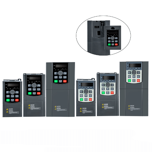
A Variable Frequency Drive (VFD) is a device based on power electronics used for adjusting the speed and torque of an electrical motor through a varying input frequency and voltage. It has three main parts: the rectifier, which changes the power from AC to DC; the DC bus, which gets and keeps the voltage at the same level, and the inverter, which converts the DC back to variable frequency and variable voltage AC to drive the motor. The elements just mentioned go in parallel to ensure that motors operate very precisely which means there is a huge increase in the motor efficiency, a decrease in the energy consumption, and a much longer life for the motors. Hence, it is extremely important to grasp the technicalities of these elements for proper application and service of VFDs in electrical systems.
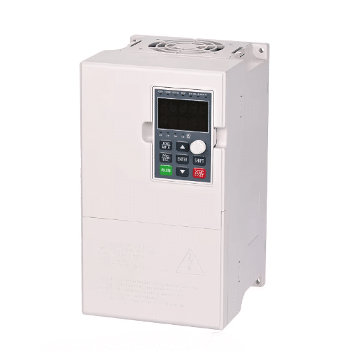
A Variable Frequency Drive (VFD) is an innovative machine that is meant to control the speed and the torque of an electric motor by modifying the frequency and voltage of its power supply. As the driving force behind motor operation is now in the hands of the operator, VFDs help to get the maximum out of energy, and change the motor’s performance according to the load need in real-time. The new VFDs have chip-based technology and smart algorithms to get the job done with precision; hence the mechanical wear is minimized, and the efficiency is maximized.
Usually, these machines come with pulse-width modulation (PWM) systems that make the power provided to the motor highly efficient and smooth. A wide variety of industries, including but not limited to the automation, manufacturing, and HVAC industries, have embraced VFDs to an extent where they cannot imagine their operations without them. On the other hand, the same data supplies a powerful argument showing that operating a motor through a VFD can lead to an energy usage drop of up to half, thus emphasizing the critical position of VFDs in the sustainable energy management process.
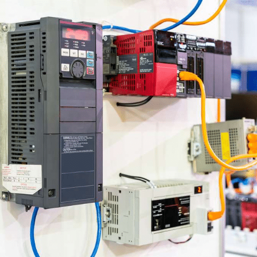
Control wiring plays a very important role as this is the connection that goes through the variable frequency drive (VFD) and actually manages it’s every function including those that are to be performed on the connected external devices, that could be sensors, relays, programmable logic controllers (PLCs), and more. This, however, requires a complex low-voltage signal transmission system which falls under control wiring and is necessary for the VFD to perform its functions making it possible to receive commands, set the speed, detect any faults and work with safety interlocks that are in place.
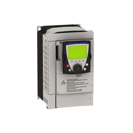
Present time graphic display systems that use Variable Frequency Drive (VFD) are very fond of possessing control terminals with common standards, which usually take care of both digital and analog signals. Only speed control is a function of digital inputs (0 – 10V, 4 – 20mA), while binary control commands that indicate forward or reverse operation are processed through digital inputs. Some of those VFDs possess extended capabilities and they are equipped with communication protocols like Modbus, EtherCAT, or Profibus which make their connection to the industrial automation architectures,.
The accuracy and reliability of control wiring significantly influence the general performance and safety of a VFD system. If the wiring is done badly, like using cables with the wrong shield or without grounding, then electrical noise will likely interfere with the signals and power or control lines could even get crossed, resulting in a malfunction. According to the specified methods of rectifying these problems, one must use the shielded cables, keep the power cables away from the control ones, and also strictly follow the drive maker’s installing instructions.
The diagrams provided for Variable Frequency Drive (VFD) systems depict the circuits in a way that no information regarding their proper installation and operation escapes. Most of the time the graphics are detailed and exhibit the control terminal layout, power supply connections, grounding points, and motor connections, in case the arrangement is more complex compared to the standard situation. The points that every drawing should have:
Whenever you are lost with the layout of the VFD wiring diagram, always have a look at the manufacturer’s wiring diagram because the layout varies between models. The accurate implementation of these diagrams is a requirement for the safe operation of the system, good performance, and compliance with the applicable standards, and the rest is not only there.
Using a three-phase VFD to control a motor is depicted via a wiring diagram that has the main components integrated for the smooth running of the system. Connecting the power input terminals (R, S, T) for the three-phase supply, the motor terminals, and the control connections are the main connections for the system. On top of that, the control circuit is also using the digital inputs for the sake of being open and close and have the very common analog voltage inputs for the least expensive speed regulation method which is actually not the best solution because it is slower and can be less accurate, but still it is quite common where speed is not a very critical parameter, 0-10V or 4-20mA.
Further elements, such as circuit breakers or fuses, can be seen on the input side, which is the protection provision for both the VFD and the motor that has been connected. On the other hand, the motor side can include output reactors or filters that reduce high-frequency noise and help in lowering the stress being imposed on the motor winding due to the voltage level. There are also EMI filters which take care of the electromagnetic interference so that the equipment is still compatible with the electromagnetic compliance (EMC) regulations in that particular region.
Regardless of how sophisticated, the control and monitoring of an entire facility can be conducted remotely by means of communication protocols like Modbus RTU or Ethernet. These give the possibility of being a part of bigger automation systems and also make it possible for the operators to make changes and carry out diagnostics in real time. It is very important that the designs strictly follow the wiring configuration and the parameter settings to the letter when using them.
When studying the diagrams of 3-phase motors, it is very important to recognize some of the most basic parts such as the terminals of the motor, the connections for the power supply, the protective parts, and the control circuits. One of the most usual setups is to join the motor windings in a star (Y) or delta (Δ) pattern, the choice being based on the needs for the operation and the voltage limitations. The star pattern is normally used for high voltage applications, the one where the delta pattern is fitting for low voltage systems and the one which provides adaptation to the wide range of electrical environments, therefore giving a certain amount of flexibility.
In a direct-on-line (DOL) starter configuration, for example, the power supply is connected directly to the motor terminals through contactors, with overload relays added for current protection. However, star-delta starters that aim at lowering the starting current of the motor, rather than DOL, use a timed switching device that begins by running the motor in a star mode before it goes to delta for the running conditions. Furthermore, most new systems use VFDs that control the speed and torque of the motor by changing the frequency and voltage of the supplied power.
The relevance of earthing and correct application of fuses and circuit breakers with respect to industry standards is very strongly underlined by every picture, as well. These electrical appliances not only make the system up and running safely but also shield the system as a whole. The schematics should be read and implemented very thoroughly through the electrical flowchart, showing all switches, relays, and connector symbols, so that the system operates smoothly.
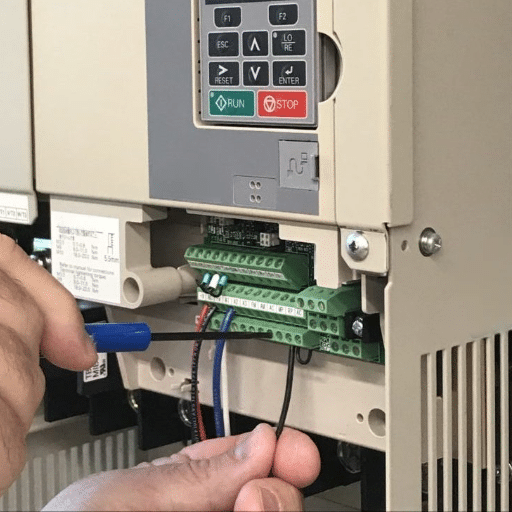
When you’re connecting the terminal wires to a Variable Frequency Drive (VFD), it’s essential to check the manufacturer’s documentation and this will help you to be assured that both the VFD and the wires will be compatible and safe. The VFDs generally have 3 main categories of terminals:
Make sure that wire sizing and grounding are done and tightened securely for terminal terminals before doing connections to avoid electrical problems that may violate the local standards. And to cause no errors, the system has to be properly labeled and serviced with the help of a wiring diagram.
Input and output terminals are the primary interface points whose correct connection and control are the vital conditions for the proper functionality of Variable Frequency Drives (VFDs). The input terminal group is typically carrying the external control signals such as start/stop commands, speed reference, and fault reset inputs. These terminals might be able to accept different types of input signals such as analog signals for improved and precise motor speed control or digital signals being sent in the form of on/off switches, depending on the particular VFD model design.
Output terminals, however, are a means of communication that besides provide feedback to linked devices or systems. Among the standard elements of the output terminals are the conditions to send the signals of fault status, speed, or working feedback by means of the relay contacts or analog outputs. There are even VFD drives that have the output terminals to be programmed so that the operation is changed according to the specific application.
Efficient integration is synonymous with the manufacturer’s technical documentation checking to ensure compatibility and precise connection methods. Each terminal should be connected in accordance with the wiring diagram, following correct electrical standards. Nevertheless, by means of thoughtful planning and execution of terminal connections not sole system performance is optimized; the protection and safety at the industrial sites are also achieved in the best way possible.
Connecting a power supply properly to Variable Frequency Drives (VFDs) is a crucial step that will provide an optimal performance and long-term reliability. The first thing to do is to select a power supply that is at the same voltage and current as the VFD needs. This is normally done by using the supplier’s data. VFDs are most commonly run by three-phase systems in their industrial applications. However, it is possible for single-phase to be used for the less powerful ones.
One thing that must be taken care of is that the input voltage is within the VFD’s tolerance, so that no overvoltage or undervoltage will occur and harm the internal parts. It is also necessary to use circuit breakers on the input side which should be rated high enough to withstand the current passing through the circuit. The connection of the wire should be carried out with the assistance of the established codes that were fixed either by the NEC (National Electrical Code) or the IEC. The cable size should be dimensioned according to the length and carrying capacity of the current.
One should connect the L1, L2, and L3 power terminals that are the supply to three-phase systems for single-phase configurations; the input power terminals marked as L and N are to be followed. To safeguard against electromagnetic interference (EMI), one of several cable selection precautions might be the use of shielded power cables. In addition, the proper grounding of the VFD case and the system is highly recommended for protecting and controlling the electricity in a much noise-free way.

For mammoth control wiring, utmost proximity to motor operation and safety is the most important thing. It would be nice if you could provide control cables that are adequate for the motor’s control circuit from the point of view of voltage and current. Usually, such cables both need and can meet the standards of the other industrial grade cables that carry the sign of the UL or IEC.
Later on, when you are engaged in wiring operations put closed and opened connections to the motor starter, relays, contactors, securely fixed so that you have no trouble with loose connections appearing later on. Standardized numbering or color codes must be used to label all the wires since this will greatly support faultfinding and maintenance. Stop your motor immediately with a normally closed (NC) stop button and start with a normally open (NO) button which is suitable for basic motor control.
To avoid signal interference in cases of longer cable runs, it is advisable to use shielded control cables, which is especially important in high EMI environments. Separate power and control wiring properly to minimize the likelihood of cross-interference also remember to always validate wiring against the motor manufacturer’s document in order to meet the system’s specific requirements.
Selecting the right wire type is very important in control wiring systems as it helps to ensure the safety and efficiency of the operation. In this case, cables consisting of multiple conductors are used for low-voltage control circuits whereby each conductor is formed by small-stranded wires thus providing better flexibility and easier routing. The cables insulated with thermoplastic or thermoset materials, rated for the operating voltage and temperature range, are most commonly used. For the circuits being exposed to high temperature or harsh environments, it is recommended to use the silicone or Teflon insulated wires as they do not only have high resistance to thermal damage and corrosion but also to the other and environment factors.
The necessity of the right grounding can not be overstated since it is the main method to protect the devices from the electrical failures and to maintain the operational stability. Therefore, it is mandatory to connect all the enclosures, panels, and metal hardware where possible to the ground using a separate protective earth conductor. There is also a need to ground bars or terminals that feature low-resistance connections in order to have an efficient grounding system. Furthermore, one must not through the neutral conductor to the ground, as it can be very dangerous and the equipment might not work properly either.
The correct and precise tagging of control wiring will help in lowering the pieces of maintenance work required at a time and thus also in reducing the troubleshooting time to a minimum. Tags, heat-shrink sleeves, or adhesive labels should be used to mark the function of each conductor without any confusion, such as “24V DC Supply” or “Motor Feedback Signal.” In the case of industrial control panels, it is also suggested to adopt the help of globally recognized standards like IEC 60204 or NFPA 79 for the purpose of wire marking and coding. Marking done according to a standard will make technicians easily understand circuit operation, even in the case of complicated systems.
The wiring done for the speed and direction control is a crucial part of a motor control system, especially when it comes to automation processes in the industrial sector. The typical wiring of such systems is more into the integration of Variable Frequency Drives (VFDs), servo controllers, or similar devices that will modulate the speed of motors and also rotate the motors in the required direction by means of carrying frequency and phase adjustment. The wiring of the system must be such that the system will be easy to manage and will use energy efficiently.
VFDs are used to control the rotational speed by transforming the input power into an output power that can be adjusted through the frequency. It is imperative to have the VFD output cables properly shielded and grounded in order to keep the electromagnetic interference (EMI) away; otherwise, EMI could have a harmful effect on sensitive equipment that is nearby. Conversely, the direction control wiring uses control inputs like Forward and Reverse signals that are mostly administered by connecting relay circuits or PLCs in order to control the motor operation. The signals dictate the direction of the motor by exchanging the phase sequences of the motor terminals.
It is very important to make sure that the wires are the correct gauge and have the right insulation, and at the same time soldering voltage and current ratings require. Improper wiring or utilization of low-quality materials may usually cause operational malfunction, high temperature, and even loss of devices. Someone should adhere to the safety and conformity requirements to prevent and solve these problems with the devices. It is really good practice to follow the industry standards which are the IEEE 1584 for electrical systems or NEC (National Electrical Code). On wire ends, it is also highly recommended to use ferrules or crimp terminations to improve the reliability of connections in terminal blocks.
In order to make troubleshooting of Variable Frequency Drive (VFD) wiring issues easier, the following steps should be followed:
Taking care of these problems in an organized way will help you find out the majority of the VFD wiring issues quickly, and safety in operations will be maintained. Constantly and carefully refer to the manufacturer’s recommendations for the specific device’s problem identification.
The connection of the VFD system is a challenge faced by many technological difficulties. Inaccurate grounding is a main troublemaker which leads to electromagnetic interference (EMI) in very many cases. EMI can spoil the work of nearby devices and cause the VFD to operate erratically unless steps for complying with EMC Standards, like filtering the lines as IEEE 519 recommends for harmonic control in electrical power systems, are taken.
Being one of the most common problems, incorrect cable selection or improper distance between the VFD and motor can be other reasons for voltage spikes. Using cables that are not shielded or those that are longer than the recommended maximum cable lengths can raise the possibility of the presence of high-frequency noise. This, in turn, could be destructive to motor windings or shorten insulation life. The solution to this is to pick cable with a low capacitance and a high shielding effectiveness, while adhering to the manufacturer’s specified installation practices.
Moreover, voltage imbalance is a problem that should be dealt with, especially in the case of three-phase systems. Variations in the phase voltages can be the source of motor overheating that might lead to diminished torque performance and can put the VFD’s internal components under unnecessary strain. One way to keep these negative effects minimal is by checking the voltage symmetry of all phases regularly.
VFD control wiring is the arrangement of the variable frequency drive connection to the motor, power supply, and it is essential for speed control of the motor. The wiring needs to have the right terminals through which the frequency and voltage can be set so that the drive can be used more easily for the speed control. Analog input or push buttons that activate speed commands and forward/reverse direction changes are the usual components that are shown in basic wiring diagrams. Energy saving and motor protection from the wrong signals are among the benefits of proper connection.
The essential terminals for a three-phase setup are the input of the AC supply, the DC bus, and the motor’s U/V/W outputs, which are properly connected and labeled in the diagram. VFD, along with other control wiring like start/stop, forward/reverse, and analog input for speed reference, can be found in industrial automation settings. Detailed basic wiring documents that clarify the connection of each terminal to the VFD and external controls are provided by ABB and similar companies. By wiring correctly, the motor works safely and fulfills the technical requirements.
Control direction terminals on the Variable Frequency Drives (VFDs) are usually digital inputs dedicated to the forward and reverse functions and those inputs can be driven by using push buttons or PLC outputs. The connection scheme indicates how to bridge or set standard terminals to the VFD where forward/reverse is to be selected. Care must be taken to ensure that the control circuit and the AC supply are isolated so as to meet the vendor’s engineering recommendations, and hence accidental activation will not happen. A motor will be regarded as correctly responding to direction commands if it has been labeled properly and thoroughly tested.
In order to wire a VFD for analog input, one should connect a 0-10V or 4-20mA signal, which is the most appropriate, to the assigned analog input terminals, and then configure the drive parameters so that it accepts the reference to the motor’s speed. The diagram will reveal which terminals will be used to control the speed; moreover, the question will also be answered as to whether an internal or external supply is needed for the sensors. Many times, a potentiometer or PLC analog output is used, being connected to the terminal that is designated for speed reference, to be controlling the motor’s speed very accurately. Ensure you comply with smart engineering methods for shielding and grounding to eliminate noise in the analog signal.