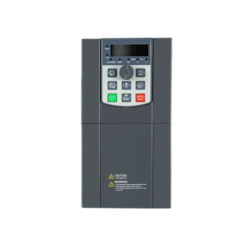
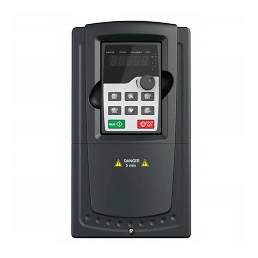
Ready to Get Your VFD Solution?
Whether you need a single drive or a complete system, we have the VFD products and engineering support to ensure your project's success.


The VFD parameter settings most likely behind nuisance trips are wrong motor nameplate data, acceleration time that is too short, deceleration time that is too short, excessive torque boost, a minimum frequency set too low for motor cooling, and protection or control-source values left at factory default. Read those first and you will clear most “mystery” trips without touching the hardware.
Marco’s team learned this the hard way on a 22 kW conveyor last March. The wiring was clean, the motor was new, and the installation looked perfect. Every time the operator pressed start, the drive tripped on overcurrent. The cause was not a short or a jam. The acceleration time was still at the 0.5 second factory default, and the motor rated current had never been entered.
You already know a VFD is only as good as the parameters inside it. This guide gives you a fault-first map of the VFD parameters that cause faults, the order to read them in, and the discipline to back up before you change anything. We will move fault by fault, not parameter group by parameter group. Want an engineer to read the trip pattern with you? The Shandong Electric team can help.
Key Takeaways
- About 60% of post-installation VFD faults trace to incorrect motor data or skipped auto-tuning, not failed hardware.
- Acceleration time that is too short causes overcurrent; deceleration time that is too short causes overvoltage.
- Keep torque boost near 2 to 3% and minimum frequency near 10 to 15 Hz on TEFC motors to avoid overheating.
- Always read the fault history and back up the current parameter set before changing a single value.
- Map the fault first, change one parameter at a time, and never disable protection to silence a trip.

Parameters are the drive’s model of the motor, the load, and the supply. When that model is wrong, the drive protects against a motor it has been mis-told about. The result is either a nuisance trip or, worse, protection that never fires when it should.
This is why a perfect installation can still trip. Industry field estimates put roughly 60% of post-installation faults on incorrect motor parameter entry or skipped auto-tuning. The fix is usually a setting, not a spare part. For a comprehensive guide to various fault symptoms, please refer to our complete VFD troubleshooting guide.
A few habits separate good commissioning from guesswork: start from a known state, enter real nameplate values, and document what you changed. Practical setup guides such as iTrustBot’s 20 essential settings agree on the same foundation, a factory reset followed by accurate motor data.
Start here when a drive trips. Find the fault, read the listed parameters, then apply the typical fix. Each row links to the dedicated fault guide for deeper diagnosis.
| Fault | Most likely parameter cause | What to check | Typical fix |
|---|---|---|---|
| Overcurrent (OC) | Accel time too short; rated current too low; boost too high | Accel time, motor FLA, torque boost | Lengthen accel, correct FLA, reduce boost |
| Overvoltage (OV) | Decel time too short; regen control disabled | Decel time, OV control, braking resistor | Lengthen decel, enable regen control, size resistor |
| Undervoltage (UV) | Ride-through or UV level mis-set | UV trip level, ride-through time, rated input | Set correct input, tune ride-through |
| Overheating (OH) | Minimum frequency too low; carrier too high | Min frequency, carrier frequency, load % | Raise min frequency, lower carrier, check fan |
| Ground fault (GF) | GF sensitivity or filter mis-set | GF threshold, carrier, cable-length settings | Tune threshold, add output reactor or filter |
| Not running (no fault) | Command or frequency source wrong | Command source, reference source, run enable | Set the correct source, verify enable |
| Communication fault | Baud, parity, address, or timeout mismatch | Network settings, termination action | Match the network settings |
Use the table as your triage index, not a substitute for the fault article. The table tells you where to look; the linked guide tells you how to confirm and repair.

If you only fix one thing, fix the VFD motor parameter setup. Five numbers must match the motor nameplate exactly: rated voltage, rated current (FLA), rated frequency, rated speed (RPM or pole count), and rated power. Enter them from the motor, not from the supply or the breaker.
Entering supply voltage instead of motor rated voltage shifts the V/f ratio and invites overvoltage or undervoltage trips. Entering breaker size instead of motor FLA leaves the motor without real thermal protection. Wrong pole count makes the reported speed wrong and confuses vector control.
Guides that focus on nameplate matching, such as this VFD nameplate data walkthrough, stress the same rule: the drive should model the motor, not the panel feeding it. Get these five values right and you remove the single largest cause of faults before you touch a ramp.
The VFD acceleration and deceleration time settings decide how hard the drive pushes the motor during speed changes. Too short on acceleration and the drive demands more current than the motor can supply, so it trips on overcurrent. Too short on deceleration and the motor regenerates faster than the DC bus can absorb, so it trips on overvoltage.
Marco’s conveyor from the introduction is the textbook acceleration case. The 0.5 second default forced a loaded conveyor to full speed almost instantly. Correcting the motor rated current and raising acceleration to 8 seconds ended the overcurrent trips that same afternoon.
Priya saw the mirror image on a high-inertia pump in Durban. A 3 second deceleration with no braking resistor pushed the DC bus past its limit on every stop. Lengthening deceleration and enabling the drive’s regen stall prevention cleared the overvoltage, the same energy path covered in our VFD overvoltage fault guide. Practical starting points by load are pumps 5 to 15 seconds, fans 10 to 30 seconds, and conveyors 3 to 10 seconds.
Enable stall prevention and overvoltage control before shortening ramps any further. Those functions let the drive pause the ramp when current or bus voltage climbs, which buys you tighter ramps without the trip.
The VFD torque boost parameter adds extra voltage at low frequency so the motor can produce starting torque. A little helps a loaded conveyor or a positive-displacement pump break away. Too much pushes the motor into magnetic saturation, where it heats up and draws excess current even at light load.
Hold boost near 2 to 3% for most applications. Reserve 5 to 10% only for genuinely high starting-torque loads, and reduce it once the motor is moving. If a motor runs hot at low speed with no mechanical reason, excessive boost is a prime suspect.
Match the V/f curve to the load while you are here. Constant-torque loads such as conveyors and hoists need a linear curve. Variable-torque loads such as centrifugal pumps and fans run cooler and quieter on a squared curve. Wrong curve selection is a quiet efficiency and heating problem that rarely announces itself as a fault.
VFD frequency limits protect both the motor and the driven machine. Minimum frequency is the one most often set wrong. On a totally enclosed fan-cooled (TEFC) motor, the shaft fan moves very little air below about 10 to 15 Hz, so the motor can overheat even at light load.
Luis ran into this on a TEFC exhaust fan that tripped on overheating every summer afternoon. The minimum frequency had been left at 0 Hz, so the motor crawled at 5 Hz with almost no cooling. Raising the minimum to 15 Hz restored airflow and stopped the trips. The same cooling boundary shows up in our VFD overheating fault guide.
Maximum frequency deserves equal respect. Never set it above what the motor bearings, balancing, and driven equipment can tolerate mechanically. Finally, use frequency jump (skip) bands to avoid a structural resonance point. A pump that vibrates hard at 47 Hz often needs only a narrow skip band, not a mechanical rebuild.
The VFD control mode must fit the job. V/f control is simple and forgiving, ideal for pumps, fans, and basic conveyors. Sensorless or closed-loop vector control gives tighter speed and torque accuracy, but it depends on an accurate electrical model of the motor. Slip compensation, where available, further tightens speed holding as load changes.
That model comes from VFD auto-tuning, the motor identification routine that measures resistance and inductance. Static tuning runs with the motor locked and is good enough for many V/f and light vector duties. Dynamic tuning spins the uncoupled motor and is what vector control really needs. Field surveys cited by AKNitech’s auto-tuning guide suggest roughly 80% of engineers skip auto-tuning or run it incorrectly.
A packaging line we supported last year showed exactly why it matters. The drive was set to closed-loop vector but had never been tuned, so the speed loop oscillated and tripped on overcurrent under light load. Running a dynamic motor identification with the load uncoupled removed the oscillation and the trips. If you are choosing a drive for a precise application, our guide on how to choose the right VFD covers when vector control is worth the extra setup.

Protection VFD parameter settings decide which faults trip and how fast. The VFD overload setting should follow motor FLA and service factor, and a correctly set electronic overload can extend motor insulation life by an estimated 20 to 40% by preventing chronic low-grade overheating. Overcurrent, overvoltage, and under voltage levels plus ride-through time belong in the same review.
Two rules keep you safe. First, never raise a threshold or disable a function to silence a trip; find the parameter that is wrong for the application instead. Second, confirm safe torque off and emergency-stop parameters are intact, because defeating safety inputs is never a troubleshooting step.
A different family of “faults” is really a control-source mismatch. If the drive will not start and shows no code, the command source and frequency reference source often disagree, or a run-enable input is left at default.
When a drive trips, read before you write. This order finds most causes in minutes and protects you from losing a working configuration. Before touching the drive, lock out and tag out the supply and let the DC bus discharge fully.
A documented parameter backup turns a four-hour recovery into a fifteen-minute restore. If you would like a second set of eyes on the readings, the Shandong Electric engineering team can interpret the trip pattern and recommend application-specific settings.
Once you find the wrong parameter, decide how to restore a known-good state. If you have a clean backup from commissioning, restore it and re-enter only the approved application changes. If you do not, re-enter from the nameplate and rebuild the ramps, limits, and protection values one section at a time.
Escalate when settings refuse to hold after a power cycle, which points to a failing memory or control board rather than a parameter mistake. Escalate too when trips persist even after every parameter matches the motor, load, and supply, because the cause is then likely hardware, power quality, or the driven machine.
For replacement drives, braking hardware, or application-specific configuration, the Shandong Electric team can size drives and parameters around your actual load, not just a nameplate.

Most repeat faults are a process problem, not a hardware problem. Back up the parameter set at commissioning and after every approved change, and keep a copy with the drive’s maintenance record. Version-control the settings across identical drives so one corrected line does not drift from the next.
Tie a short parameter review to your regular VFD preventive maintenance. Confirm that no one has “temporarily” raised a threshold, that min frequency and ramps still match the load, and that the as-left settings match the log. A five-minute review each quarter prevents the slow drift that ends in a weekend trip.
Record the as-left values on the motor and drive nameplate log. The next technician to stand in front of that drive, possibly a year from now, will thank you for it.
Wrong motor nameplate data (voltage, FLA, frequency, RPM, power) and acceleration or deceleration times that are too short cause the majority of nuisance trips. Excessive torque boost and a minimum frequency set too low are close behind.
Yes. An overload set above motor FLA removes thermal protection, excessive boost overheats the windings, and a maximum frequency set above the motor’s mechanical limit can damage bearings and balance. Parameters are protection, not just performance.
The acceleration time is usually too short for the load inertia, the rated current is set too low, or torque boost is too high. Lengthen the acceleration time, correct FLA, and trim boost.
The deceleration time is too short, so the motor regenerates faster than the DC bus can absorb. Lengthen deceleration, enable regen or overvoltage control, or add a correctly sized braking resistor.
Yes. Vector control depends on an accurate motor model from auto-tuning. Running vector without motor identification commonly causes speed oscillation and overcurrent trips.
It keeps a TEFC motor running fast enough for its shaft fan to cool the windings, typically 10 to 15 Hz. Set too low and the motor overheats even at light load.
Not as a first step. Read the fault history and back up the current settings first. A factory reset erases the very clues you need and should only follow a confirmed backup.
Read the fault code plus the frequency, output current, and DC bus voltage captured at the trip. Those three values usually point straight to the parameter that is wrong.
Most mystery trips are not failed hardware. They are a parameter that does not match the motor, the load, or the supply. Get the VFD parameter settings right by reading the fault first, mapping it to the likely setting, backing up, and changing one value at a time.
If a drive keeps tripping after the settings are correct, the cause is hardware, power quality, or the machine, and we can help you isolate it. Contact the Shandong Electric engineering team for application-specific parameter recommendations, or browse our Shandong Electric VFD product range for drives sized to your load.