Ready to Get Your VFD Solution?
Whether you need a single drive or a complete system, we have the VFD products and engineering support to ensure your project's success.

Proper selection of components is crucial when dealing with Variable Frequency Drives (VFDs) for obtaining the best performance, managing efficiency, and maintaining the system in good condition. Among several things, rectifiers, inverters, and filters are considered part of the most important components for delivering specific motor control and resolving power issues. This paper will go into all the technical detail of each of these components and just how much influence they can have on the overall operation of a VFD system. If you are designing a system or working on the system already up and running, this paper will furnish you with enough information to make reasonable decisions. Please gather around insight and tactics for selecting the most suitable rectifiers, inverters, and filters for your application of VFD systems.

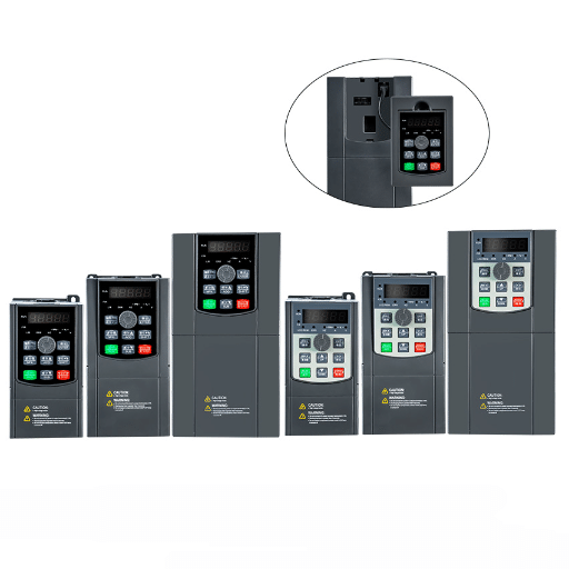
Variable Frequency Drives (VFDs) are electronic devices that enable the control of electric motor speed and torque by changing the frequency and voltage being supplied. This control is possible by means of the three main parts:
Working together, VFDs allow saving energy consumption, improve motor performance, and reduce wear and tear on machines. They are a pivotal item in modern industrial and HVAC applications.
| Component | Function |
|---|---|
| Rectifier | Converts incoming AC power to DC power. |
| DC Bus | Stores energy in the form of DC voltage. |
| Filter Circuit | Removes electrical noise and stabilizes DC power. |
| Inverter | Converts DC back to adjustable AC power. |
| Control System | Manages VFD parameters and motor performance. |
| Cooling System | Prevents overheating of VFD components. |
| Input Protection | Protects against surges, overcurrent, or voltage spikes. |
| Braking Resistor | Dissipates energy during rapid motor deceleration. |
| Interface Module | Enables communication with external systems or networks. |
| Feedback Sensors | Provides real-time motor and system data for adjustments. |
The inverter control system determines the operational properties of the VFD system, such as motor speed, torque, and direction. It is responsible for processing the input signals and executing algorithms in order to ensure fairly consistent motor performance that can adapt to changes in the load. In some advanced cases, such control systems have installed predictive maintenance software for longer system life.
Overheating provides a disastrous situation for high-power VFD systems. The cooling system employs heat sinks, blowers, or even liquid cooling for the power electronics to make the safe exit of excessive heat produced. Optimum temperature control becomes necessary for ensuring operation continues, minimizing the potential damage to electronic system elements, and extending the VFD life.
The electrical disturbances experienced by a VFD, which may vary from time to time, are electrical surges, spikes, or various overcurrent events. In order to prevent such disturbances, which might otherwise fry the sensitive internal circuits of the VFD, an input protection system applies various components like fuses, surge arresters, and circuit breakers, all in full compliance with the regulation provided.
End brisk deceleration or braking through resistor is a prime precondition. Wherein the resistor will convert the extra electrical energy which is returning to the motor right into heat. It shall be dissipated safely, ensuring no overvoltage in the system.
The interface module was especially developed to facilitate communication as well as willing merges into external systems since it supports large number of protocols such as Modbus, EtherNet/IP, PROFINET, etc., enabling easy and seamless connection to programmable logic controllers (PLCs) and SCADA systems, thereby setting the overall control and surveillance.
Feedback sensors, such as the encoders, resolvers, and current sensor, provide real-time data on the speed, position, and torque of the motor. This information is used by the VFD for fine adjustment to maintain higher efficiency and performance to ensure stability of each and every electrical circuit during its dynamic operating conditions.

Rectifiers offer the substantial responsibility of converting AC (alternating current) power from the grid into a direct current power in a Variable Frequency Drive (VFD) system. This conversion is indispensable for forming a stable intermediate DC voltage, to be used as a base by the inverter section to produce variable-frequency AC power for motor control. Most VFD systems comprise either diode-based rectifiers to keep good levels of simplicity and price, or active rectifiers to unleash advanced control features such as reduced harmonic distortion and enhanced power factor; the rectification process itself directly affects the efficiency and operational reliability of the system, emphasizing the rectifier as one of the very core components of VFD functionality.
| Feature | Diode Rectifier | Thyristor Rectifier |
|---|---|---|
| Control Capability | Fixed output voltage | Adjustable output voltage |
| Complexity | Simple design | More complex design |
| Cost | Low-cost | Higher cost |
| Application | Common in standard VFD systems | Used in high-power industrial applications |
| Efficiency | High efficiency | Slightly lower due to control losses |
| Harmonic Distortion | Higher harmonic distortion | Lower with phase control |
| Power Factor | Lower power factor | Can achieve better power factor |
| Switching Control | Operates automatically, no external control needed | Requires external gating signals |
| Response Time | Relatively fast | Slower due to gating mechanism |
| Use Case Example | HVAC systems, small pumps | Steel mills, cement plants |
The rectifier type chosen directly impacts the introduction of harmonic distortion into the electrical system. Less-controlled rectifiers, like the diode rectifier, normally output more harmonic content with fixed switching features and no external control. The harmonic currents they unfortunately produce disturb delicate equipment while worsening the power quality and resulting in poor efficiency losses of the system. On the contrary, controlled rectifiers such as thyristor-based systems can allow for phase control, which can provide a reduction in the harmonic content by adjusting the timing of the gating signal in meeting more closely the system’s demand.
Modern power systems seem to be designed to throttle down the known harmonics through passive or active filtering gradually. And this may result in the Total Harmonic Distortion (THD) settling down just to IEEE 519-2014 limits. By increasing the rectifier technology like 12-pulse or 18-pulse, it is a well-better multiplying system to undertake solutions for harmonic cancellation by displacing harmonics to higher multiples hence lessening their footprint all the way back away from the grid. Selecting a rectifier requires an in-depth analysis of load restrictions, the nature of the application environment, and relevant regulation to ensure practical and functional effectiveness within the harmonics limit environment.

The competitive world is spiraling at full pace. All in all, most of us have embraced its stepping stones and made new mechanisms from where we are currently leaping into the universe of artificial intelligence. A career is distinguished by whether or not we are comfortable with the registration of data on all flow channels generated as an extension of computers’ willingness to assume the control for brain functions, image recognition, and speech production. The more we are proceeding with the development of relevant intelligence abilities, the more we get enjoyment.
| Inverter Type | Description | Key Features | Applications |
|---|---|---|---|
| Voltage Source Inverter (VSI) | Converts DC to AC using voltage control. | High efficiency, simple design. | Pumps, fans, conveyors. |
| Current Source Inverter (CSI) | Converts DC to AC using current control. | Robust, high reliability. | Large motors, industrial processes. |
| Pulse Width Modulated (PWM) | Uses switching pulses to generate variable output. | Precise control, low harmonic distortion. | General-purpose VFDs. |
| Multilevel Inverter | Generates AC from multiple DC voltage levels. | Reduced harmonics, high power rating. | High-power applications, utility grids. |
| Resonant Link Inverter | Operates with a resonant circuit for efficiency. | Compact size, energy-efficient. | Specialized industries, robotics. |
| Matrix Converter | Directly converts AC to variable AC power. | Transformer-less, regenerative capabilities. | Aerospace, compact VFD systems. |
The inverter technology represents a major influence on energy efficiency and overall power consumption in electrical systems. Operation of power conversion efficiency in various inverter topologies might be significantly impacted. As an example, the multilevel inverters are recognized with their characteristic low harmonic distortion, resulting in a lower loss in energy and an increasing performance. This realization makes them extremely efficient in large-scale renewable energy systems like solar or wind farms.
Resonant-link inverters deliver optimized energy usage by integrating a resonant circuit. Use of a resonant circuit minimizes switching losses, so they serve as majorly efficient and small-package solutions for those industries that require high efficiency of their electronics, including robotic and medical market sectors. Besides matrix converters remove the way for transformers to get rid of energy losses by transmitting energy in both directions. Particular regenerative features make the operation of a matrix converter easier in applications including aerospace and high-performance motor drive systems, where energy control fluctuates fast.
When choosing inverters, it is essential to assess several technical and operational drivers to ensure the intended purpose aligns with potential equipment selection. One of the most significant factors to consider is power rating, which works best if it is in line with the anticipated current demand of the connected load, with the least chance of overload or inefficiency. Even an essential aspect is how well the inverter interconnects with the supply voltage level and single-phase or three-phase systems for maximum interoperability.
Furthermore, efficiency matters a lot when selecting inverters. It is useful with high-efficiency inverters to limit energy losses and thermal output, enhancing the overall performance of the system whilst reducing operational costs. When looking for inverters, search for an approved rating of their efficiency in internationally recognized Standards or compliance under a program such as the IEC 61683 standard or STAR compliance.
Managing temperature demands attention to thermal matters. Diurnal extremes demand innovative procedures for cooling and high-impact designs suitable for sustained performance, especially in demanding industrial or open-air conditions. Consider also the total harmonic distortion (THD) of the inverter for these sensitive locations, and the THD could degrade equipment life performance.

Harmonic and filtering measures are vital for the warranty of power system solutions reliability as well as power efficiency. Harmonics are blocked from the network through filtering, thereby positively depicting power quality. Intended to mitigate the distortions, active filters have their settings dynamically adjustable, providing instantaneously ongoing denial of harmonics; passive filters are a very cost-effective way to address non-varying situations. Implementing such correction measures will improve power conditions and ensure compliance with international standards like IEEE 519 (to give directives about harmonic control within electric power systems). Regular system-analyzing and monitoring functions are a must to ascertain that the filters are working in their best capacity and keep harmonic levels well confined within acceptable margins.
Harmonic filters have become indispensable in price maintenance of Variable Frequency Drive (VFD) systems equipped to make protection against the detrimental effects of harmonic and other current distortion. This distortion was introduced by nonlinear loads like VFDs, introducing what is known as harmonic current—a higher-order frequency present on top of the fundamental “good” waveform. Such distortion, if left unattended, gets rid of the best equipment liability and hampers efficiency; it can also result in the breakdown of costly electrical machines as well as a catastrophic reduction of system reliability.
Modern harmonic filters, either passive or active, are necessary to meet global electrical standards and enhance the system’s performance. Passive harmonic filters use fixed components (resistors, inductors, capacitors) to eliminate specific harmonic frequencies, while active harmonic filters use fast electronics to eliminate harmonics dynamically over broad frequency bands. Research has demonstrated that the integration of any of these filters can assist in reducing Total Harmonic Distortion (THD) by up to 95%, improve the lifespan and the performance of the power system.
Not just that, but also the return on investment for harmonic filtering is high. By lowering the possible chance of unscheduled downtime and reducing unnecessary energy wastage due to harmonics produced, considerable savings are seen by businesses over time. Markets with a great concern for the quality of power, such as manufacturers, medical care, and data centers, continue to adopt harmonic filters in their VFD systems to ensure that power remains undisturbed and the maximum utilization of power is achieved. A combination of wisely designed proactive systems that can be kept in robust health through perfect maintenance and monitoring is no less important for augmenting the benefits of harmonic filtering in VFD applications.
| Feature | Passive Filter | Active Filter |
|---|---|---|
| Technology | Uses fixed components (inductors/capacitors) | Utilizes power electronics and controllers |
| Harmonic Range Addressed | Limited to specific frequencies | Wide range of harmonic frequencies |
| Installation Cost | Lower | Higher |
| Energy Consumption | Low | Moderate to high depending on load |
| Adaptability to Load Changes | Less adaptable | Highly adaptable |
| Maintenance Requirements | Minimal | Requires regular monitoring |
| Response Time | Slower | Fast, real-time correction |
| Footprint | Larger due to bulky components | Smaller, compact design |
| Efficiency Impact | Can cause slight efficiency loss | Improves system efficiency drastically |
| Best For | Stable loads with known harmonics | Dynamic and variable load environments |
Having with you an appropriate Variable Frequency Drive (VFD) is necessary to ensure that the choice made meets with the system’s needs and serves the purpose accurately. Points to dwell on should include the following:
On the basis of the aforementioned criteria, a VFD can be selected that best enhances performance, reliability, and efficiency for a specific application.
Variable Frequency Drives (VFD’s) utilize several methods of control to obtain precise regulation of motor speed and torque. The choice of these methods directly influences the efficiency, operation, and, from a large perspective, performance of the entire system. Here are the main control methods that one might use in the case of the most frequently utilized VFDs:
V/F control is a control method where constant flux is maintained in the motor by maintaining a constant ratio of voltage to frequency to ensure operation at the same flux level. It is simple, cost-effective, and quite limited in its dynamic capability to cope with quick adjustment, so it is used only on applications with medium accuracy requirements, such as fans or pumps.
Unlike V/F control, OLVC has a thorough improvement in performance compared to the V/F control, and in the software algorithm, can adjust the torque value of the motor in real-time without any feedback loop. Such control provides explicit torque control and can be applied to applications such as belt conveyors or mixers, where full closed-loop accuracy is not of that much importance.
In this method, implementing feedback devices like encoders and resolvers ensures the true control of the motor by means of continuous and automatic monitoring and adjustment of the motor’s parameters during operation. This method is necessary for speed and torque control applications requiring high precision, hence its typical usage in the robotics industry, elevators, and CNC-type equipment.
Among others, it is particularly well appreciated for its outstandingly fast response and high efficiency. DTC directly bestows control of motor torque and flux without the need for difficult and complex calculations of voltage. This method is predominantly suited for applications demanding fast dynamic performance with minimal torque ripple and enhanced energy efficiency.
Different control methods fit different operational scenarios and performance requirements. Consider elements like motor type, load dynamics, operating requirements, and system integration complexity when selecting a control method. The VFD shall exploit the method of choice to optimize motor performance and shall make motor life an efficient affair.
A Variable Frequency Drive (VFD) is an apparatus upon which motors run and control their speed by varying frequency and voltage so that precise speed and process control can occur. In doing so, the energy consumption in variable torque applications such as pumps and fans can be greatly reduced. Since adjustable frequency and voltage enable VFDS to operate at the power/motor state very efficiently, these features allow motors to produce only as much energy as is necessary to power in order to lessen the wastage of energy. A VFD possibly becomes less energy efficient by reducing speed to approximate the load and therefore lowers power consumption and can also enhance power quality aspects when filters are properly employed.
Further considerations related to matching the VFD to the application in respect of the right VFD type for the job and making sure the vfd and motor fit in with the motor’s power rating and intended speed control reflect whether the process control aims at variable speed or closed speed regulation and whether variable torque or constant torque operation is required as different classes of VFDs and output filters will produce different voltage and frequency at their output. One case in point would be the AC input requirements, since the VFD takes AC power and converts it to another frequency and amplitude by changing its frequency.
Line reactors and output filters reduce harmonics injection into the power system by smoothing the voltage on the power supplied and limiting the switching noise that VFDs introduce into the power. Filters, reducing the harmonic content to negligible levels, prevent high-frequency content from reversing back to the electric grid improving Power Quality issues to a great extent. Voltage output filters as well as line reactors help protect induction motors and extend the motor life by producing a cleaner voltage output and frequency to the motor. The selection and proper installation of filters prevent potential damage due to reflected waves and ensure that the VFD operates within the desired limits of frequency and voltage.
Commonly used to control the motor speed, variable frequency drives adjust the output frequency and voltage so as to allow for speed and process control in engineered solutions beyond the capabilities of fixed-speed drives. By converting AC power to DC power and then again inverting DC to a controlled AC output, VFDs can adjust the output frequency and voltage dynamically to match the target process specifications in real time. This will save energy costs and maintain the quality of the product by keeping the process running optimally under diverse load conditions. In many cases, VFDs are capable of keeping energy waste and equipment wear to minimal levels with while doing a smooth acceleration or deceleration.