Ready to Get Your VFD Solution?
Whether you need a single drive or a complete system, we have the VFD products and engineering support to ensure your project's success.


By the use of Variable Frequency Drives (VFDs), industries can effectively manage energy use, improve motor efficiency and hence, be more competitive in the market. Nevertheless, the benefits might be lost due to wrong ways of installation, causing not only stoppage but also hazards and equipment damages. The guideline below will help you in avoiding the industry’s most common installation mistakes and at the same time lead you through the installation process to make it more dependable. This is whether you are a professional in the field or you are a facility manager, as this material is ready to arm you with necessary information for the purpose of errors avoidance and equipment performance. Follow the next lines to the end to catch the main principles and the latest approved methods of the cause of a successful VFD installation.
In modern industrial applications, Variable Frequency Drives (VFDs) are indispensable and they have been designed to run electric motors at the right speed and torque. The importance of their proper installation lies in the fact that this will not only optimize performance but also extend the life of the equipment and ensure safe operation. The installation process involves several steps: choosing the VFD that falls in line with the motor’s specifications, making sure the wiring and grounding are correct, and setting the drive parameters in accordance with the requirements of the system. If the installation follows the manufacturers’ recommendations and the standards like IEEE and NEC codes, the risks will be very low. There are lots of various problems users face when using VFDs and in some cases a preventive approach will be the best treatment.
The installation of Variable Frequency Drives owing to its perfect compatibility and performance has a significant impact on the production cost and quality of the power system in the long run. Data centers are one of the most common applications in which VFDs can be used as these are large and have a great number of motors. They are of course not the whole list of applications but most of the time are definitely among them. An example is the installation of VFD in a cooling system of a data center. Can you add your expertise and the other applications as well, please? By stating that the selection of the motor, drives, and controllers are under the scope of the project already. The soft starter can increase the lifetime of the installed motor but there are, of course, some other ways to do that which need to be agreed: choosing the right bearings and insulation classes, adding motor protection such as different types of relays, and so on.
Thermal management inside the control panel is of similar importance. It has been acknowledged more and more closely in the past ten years that incorrect or inefficient cooling is a major factor in the reduction of the variable frequency drive (VFD) rated power or the life of the components. Provision of ventilation systems and leaving enough space between the drives and other components are now to be regarded as remedies of common use. The right selection of cable shielding and grounding systems will ensure you meet the electromagnetic compatibility (EMC standards, ensuring you of a crucial factor for places where industrial performance is crucial.
VFDs are very important parts of current industrial and commercial systems as they offer the best command over motor speed and torque. They can save a big amount of energy in many variable load applications like pumps, fans, and conveyor systems, by changing the frequency and voltage given to the motor. Moreover, this feature will not only reduce energy use but it will also lengthen the life of the motors as it will put them through much less mechanical and electrical stress during the start-up and operation of the driving system.
Enhanced digital interfaces, improved thermal management systems, and the integration of intelligent diagnostics are some of the recent developments in VFD technology. These traits provide real-time monitoring, predictive maintenance, and ease of integration into Industry 4.0 setups. Besides, industry standards and energy efficiency regulations have become the parameters to which VFDs regularly adhere, thus they have been recognized as a dependable and future-proof solution for active industrial requirements.
Poor install of variable frequency drives (VFDs) may lead to big performance issues and also failure of equipment. One of the most usual errors is not to ground and shield properly, which may cause electromagnetic interference (EMI) that troubles the sensitive equipment near and controls. Further, the occurrence of the wrong wiring or a loose connection may bring about voltage spikes, consequently, resulting in the failure of the motor insulation or even very big breakdown. The lack of attention to the environmental factors like temperature, humidity, and dust might directly lead to VFD overheating, condensation problems, or contamination, causing a big reduction of the unit’s lifetime. Yet another mistake is to choose a VFD that does not match the motor and load requirements. This may render the system inefficient, opportunity to experience faults on the line side and not capable of varying loads. It is evident that there are many issues that support the fact that one of the things vital in the installation process is following the manufacturer’s conditions, doing thorough site surveys, and the selection of competent technicians for setup who would be able to make the system perform as expected while the problem of reliability is also well dealt with.
Improper sizing of the Variable Frequency Drive (VFD) can result in different types of problems like inefficiency, damaged equipment, and system performance that is not optimal. A VFD which is too small compared to the motor’s demands could get too hot, cause several overload situations, or break down earlier because of the overstrain on its parts. Consequently, having a too big VFD might increase the power consumption, unjustifiably leading to much higher starting expenditures that do not bring about any system performance gains.
To properly size a VFD unit one must go through the full-load current, and analyze the voltage, weather conditions while the operational state of the motor and its load type is maintained as well. With high-torque equipment, such as conveyors or crushers, VFDs that have extra current capacity during the starting or load surges are often needed. Moreover, it is common in the industry to allow a design margin for applications that may be affected by VFD function due to environment factors like temperature, dust, or altitude. The use of tools such as flux current ratings and drive efficiency benchmarks is very important in the optimization of the system configuration and at the same time minimizing the losses of energy. Proper sizing, in the end, can lead to greater system reliability, gear life extension, and increased energy efficiency on a global level.
The disregard of the motor data in the VFD applications might result in a great deal of operational inefficiency and equipment failure. Motor nameplate data that includes voltage, current, power factor, and nominal speed are vital in programming the VFD correctly and its optimal operation. If you do not have this data, the VFD might fail to meet the operational requirements of the motor causing such problems as torque instability, overheating, or high power consumption.
An instance is when overload protection parameters are being set without rating of a motor’s current, it can result in a motor getting overheated and subsequently reducing its life expectancy. Moreover, if voltages and frequencies do not match the motor’s specifications, less than proper performance can be experienced, i.e., spontaneous and non-permanent turning of the motor or derating. The majority of modern Variable Frequency Drives (VFDs) employ specialized algorithms, such as vector control, which in turn require precise motor data; hence, some applications are speed- and position-controlled with the help of these VFDs. Meanwhile, modern VFDs also rely on specialized algorithms sometimes including vector control that demand the motor parameters to be very high. Incorrect or missing data interfere with these algorithms, causing a loss of performance and accuracy in applications where there is a need for a steady control of the speed and positioning.
The proper selection and management of cables is important for the efficient and reliable operation of VFD (Variable Frequency Drive) systems. Various problems may arise from using cables that are not meant for VFD applications, such as the occurrence of electromagnetic interference (EMI), voltage spikes, and heating problems which can harm both the motor and the drive. High-performance VFD cables are made with the right shielding and insulation to eliminate EMI and protect against the interruption of the signal in sensitive areas.
Inadequate cables might exacerbate the system deficiencies even more. For example, the cables that are too small will heat the system up excessively because of the higher resistance, thus, on the one hand, risking the insulation breakdown and potential electrical faults, while, on the other hand, the cables that are too large will cost more and also take away the installation flexibility. Moreover, incorrect cable routing—e.g., placing power cables nearby sensitive signal or control lines—may add noise to the system, which will lead to not only degradation of the signal and hence reducing the operational stability but also operational downtime due to the faults caused by the noise.
Our VFD system needs good performance to the maximum extent so proper, dedicated cables are very crucial. The ideal cables should not only have the specified insulation class but also be armored adequately against environmental conditions, and support the current-carrying capacity as stated in IEC and UL standards, for example. Besides, the elimination of voltage reflections and the consequent enhancement of the system’s overall reliability are the main reasons for the continuation of following proper grounding and termination practices indicated in the IEC and UL standards. Regular checks and cleaning of the cable systems are the practices that maintain their performance during operational forces.

One has to consider the environment in which the Variable Frequency Drive (VFD) will be installed so that there is an assurance that it is mounted in a safe place, free from too much vibration, and with no direct sunlight or heat source. There should be the presence of proper ventilation, which is a necessity, so that the minimum clearance will be the one provided in the manufacturer’s specifications, thus ensuring unrestricted airflow and overheating prevention. When between walls of the room where the VFD is to be fixed, it is good to confirm the material of the casing and if it can withstand high temperatures and conditions such as less or no air, no dust or moisture in the box.
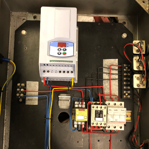
According to the manufacturer’s wiring diagrams, make sure that all the electric current flows through the same paths and adhere closely to both the primary and secondary power connections. Try and untangle cables and label each one with its own voltage and current rating, plus check for electromagnetic interference (EMI). In the case of EMI shielding, make sure grounding is done properly and according to the guidelines of the NEC or IEC respectively, so as to prevent any electrical noise and support the system’s safe operation by protecting from lightning, etc.
Making sure a Variable Frequency Drive (VFD) is working properly is a complex and detailed process that needs to be done correctly to guarantee that the equipment will have a long life. One starts by checking if all electrical connections are properly connected, and that the cables are in accordance with specifications given by the manufacturer and the local electrical codes. The voltage of the input power, the current of the output power and the method of grounding are the three main problems, so it is imperative that the connections are done correctly otherwise these problems might lead to inefficiency or dangerous conditions.
Run the power cables through an insulation resistance test to ensure that they are up to standard and that there has been no compromise in the insulation during the installation. Moreover, make sure that the control wiring is in line with the required functionality as per the application design. As to signal and control cables, they should go through different routes from the power cables for the purpose of reducing the possibility of interference and to protect the signal from being altered.
Inspect the parameter settings and make sure they match the requirements of the application, like motor ratings, acceleration and deceleration times, and frequency limits. It is essential to check these parameters as that will the most vital part of keeping operational errors away and protect both the drive and the motor.
At last, check the no-load test to ensure the VFD and motor are functioning with a load. Next, go for the gradual load test and all the while, be mindful of a number of the system’s indicators such as current draw, output voltage, and motor speed stability to guarantee that the system is being used properly as outlined in the design. The use of manufacturer-recommended monitoring tools for the tests can mean help in pinpointing any irregularities and resolving them. Without proper documentation of settings and test findings, there will be an issue in doing maintenance and solving problems.
One of the major factors in the provision of the reliability and effectiveness for the control and machinery of the complex system is the onsite troubleshooting. The technicians get the full access of local conditions such as environmental conditions, installation practices, and system interactions, which can affect performance, by diagnosing the problems at the place where the machine is operating. Doing so and hence, applying the proposed solutions can effectively cope-up with the original issues. This route also will give you the benefit of continuously monitoring your system as being equipped with monitoring tools, plus getting chemical composition and air suction reports are also possible through the various sensors in the operational room. For example, in chemical plants, besides the plant information sheets that are prepared prior to the operating plant, exact on-line monitoring leads to information that is more accurate. Regularly, the main machine, as well as its support, such as the tower and tank system from the air separation plant, went down (its pressure dropped to “atmospheric” levels) for this reason.

Electromagnetic interference (EMI) is a critical factor to take into account when installing variable frequency drives (VFDs) since it may negatively affect the operation of nearby electronic equipment. The following are some of the key practices to effectively mitigate EMI:
Following the above steps at the time of installation will not only assure the system’s reliability and conformity with the EMI requirements but will also protect the equipment’s function and operation efficacy.
Electromagnetic interference (EMI) has different sources but can be broadly divided into natural and man-made sources. The first one includes conditions of lightning, bursts of solar radiation, and disturbances in the earth’s magnetic field, all of which bring forth electromagnetic waves of high-frequency causing interference with electronic systems. Conversely, devices and industrial procedures are the bases of human-made interference. Examples of equipment which often emit electromagnetic waves such as motors, power lines, radio transmitters, and variable frequency drives (VFDs), either intentionally or as a by-product produced by their nature of operation.
It is the detection mode of the interference that is a big concern when it comes to EMI. Commingling is the mechanism of propagation for conducted interference. Though power lines or signal cables are the media, radiated interference is the culprit that transmits the disturbances. Both scenarios have exclusive measures for the protection of the systems; those measures are the facilities where the performance of the equipment is critical the most. The latter are such as the industrial plants, hospitals, and data centers.
Not only this, but the interference’s frequency is another parameter to differentiate it by. Among the two, the high-frequency EMI affects the devices in a way that it may cause a problem in the wireless communication and impair the functionality of the precision instruments. The converse is true with the low-frequency EMI, as it mainly affects the power systems. The proper understanding of these factors can serve as a basis for the implementation of shielding and other measures such as grounding, filtering, which are essential in maintaining the integrity of signals and the reliability of the overall system.
A perfect way of electromagnetic interference (EMI) shielding is the combination of effective materials, technical engineering and a system analysis all together. Additionally, if the right variety of materials is used then the choice of such materials serves as the best and foremost method of EMI shielding. The use of standard shielding materials also goes a long way in ensuring that the sources of the emissions are minimized. Copper, for example, is a very good attenuator and can be used over a wide frequency band, while light-weight composites may serve the cause better in weight-sensitive applications.
The design of the shielding should be approached in a manner that the existing gaps, seams, or joined components are given careful consideration. The usage of overlapping seams, conductive gaskets, or other techniques such as soldered joints have a dramatic effect on the overall EMI shielding capability of the system. Moreover, the practice of multilayer shielding combined with integrated systems helps in providing stronger electromagnetic wave walls.
The importance of grounding and bonding holds equal value; systems with insufficient grounding, in fact, can worsen EMI problems rather than solve them. A low-impedance ground must be used to bond shielded enclosures to, thereby removing unwanted electromagnetic energy through that way in a safe manner. Moreover, the usage of EMI filters at the points of entrance of the cables is an effective way to block off signals from the shielded zones via the wires or cables that are connected to those same points.

The improper grounding or inadequate shielding material coverage are the common reasons for shielding failures. To take care of the problems:
These corrections are usually very effective in solving most of the shielding-related EMI problems.
There are several identifiable symptoms of installation errors related to electrical and shielding systems. These symptoms can potentially affect the performance and reliability of the whole system. One of the most prevalent signs is the unexpected appearance of electromagnetic interference (EMI), which can lead to errors in the signal transmission or even the disabling of the communication channel. It may be boring to mention, but if shielding and grounding are not dealt with properly, it could be the reason behind the problems. Moreover, irregular system operations like, for instance, equipment that resets itself at intervals and causes communication gaps suggest that the cables are not managed well or the connectors are not in the good condition. Audio or signal lines’ increased noise would be a sign of noise coupling, a phenomenon mostly contributed to by shielding lapses or the lack of adequate filtering. One of the most effective ways to know if your system is performing as expected is to carrying out a thorough examination of it for any physical faults, and one of the critical ones of these inspections which must be done is looking for any exposed or poorly fixed shielding materials.
When it comes to solving complicated problems, a systematic manner is a must. The first step is to divide the system into distinct parts that will make it easier to detect where the problem is coming from, and for this, the measurement instruments need to be used appropriately. For example, when it comes to the electrical system, its continuity and the impedance should be checked first and then the actual fault will quickly be known. Making logs and faults and comparing with the technical specifications of the manufacturer and the benchmark of the calibration in order to make sure that the system is up to the standards from the beginning.
Deploying sophisticated monitoring systems based on real-time telemetry data is another factor helping in complex problem investigation, and it facilitates monitoring the performance of the pieces of equipment at different operational conditions. Furthermore, the use of static and dynamic testing techniques is a must for investigating components separately and at the same time subjected to system load simulation. The combination of these methods guarantees a 100% fault-proof solution, thereby reducing downtimes to a minimum and retaining ideal operation conditions.
The prevalent errors when it comes to VFD installations which are the choice of wrong cables, wrong termination point, and grounding of both the power and control cables that lead to interferences are the most irritating type of problem. To prevent VFD wiring issues, create a distance between power and control wiring, adopt the use of shielded communication cables, and always be strict in following the cable length and type specifications provided by the manufacturer. The positioning of the cables should be done in such a way that vibration and mechanical stress on the terminations are minimized. Make a last round to check if all connections are firm and rust-free before putting the power on.
Providing the proper grounding points for the VFD systems is mandatory. They not only provide a ground path, but also help maintain the ground as required. A ground loop might be formed, the protection of which would be the usual practice through the use of filters. One potential source of interference to the system is the stray current. Errors due to the wrong grounding method will be avoided if proper grounding is provided and the required working current is led away from the neutral conductor. Bonding the drive mains feeding facilities to the earth main grounding plate is also a good practice, thereby eliminating interferences and their effects through the drive’s circuits.
In order to increase the motor’s lifespan and prevent motor bearing faults, it is recommended that the VFD output characteristics and filter options be matched with the motor drive requirements. Additionally, shaft grounding or insulated bearings may be considered. The motor cables given should be the right ones, and the shortest practical cable length should be maintained in such a way that the reflected wave overvoltage is minimized, which can be the cause of stress to both the motor insulation and bearings. The ramp-up and ramp-down parameters should be set so as to prevent abrupt changes in torque that will cause wear in the mechanical components.
Parameter programming errors typically result from disregarding the default settings that are not optimal for the given situation, like in the case of wrong motor data in the nameplate, overlong starting and stopping times, or the current resistances that are too low. To do everything correctly, the first step is to enter the exact motor data given in the nameplate, then, if possible, tune the motor control loop, and finally, make sure that the settings are correct by running tests with a real load. Every change in parameters must be committed to paper and a copy of the drive setup must be made after the operation is successful.