Ready to Get Your VFD Solution?
Whether you need a single drive or a complete system, we have the VFD products and engineering support to ensure your project's success.

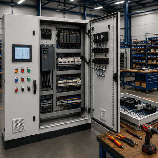
An industrial VFD system is more than a single drive. It is an integrated assembly of the VFD, motor, power cables, input protection, output filtering, braking components, and control interfaces that must work together as a unified system. When any one of these components is underspecified or incorrectly installed, the entire system fails — even if the VFD itself is a premium unit.
A food processing plant in Brazil learned this the hard way. They installed a 200 kW VFD on a centrifugal pump. Within eight months, the motor bearings failed catastrophically. The VFD diagnostics showed zero faults. The culprit was not the drive. It was the 120-meter unshielded motor cable that created voltage reflections strong enough to damage the motor insulation. A 400outputreactorwouldhavepreventeda400outputreactorwouldhavepreventeda12,000 failure.
If you are a system integrator, plant engineer, or project manager responsible for specifying and commissioning industrial VFD systems, this guide gives you the complete architecture. You will learn every component in the system, how to select each one, and how to avoid the peripheral failures that destroy drives that are otherwise perfectly functional.
Key Takeaways
- An industrial VFD system includes seven core components: the VFD, motor, power cables, input protection, output filtering, braking system, and control/communication interfaces.
- Cable length matters. Runs over 50 meters without output filtering can produce voltage spikes of 2-3x nominal voltage at the motor terminals.
- 40-50% of VFD downtime is caused by peripheral system issues (cables, grounding, cooling) rather than drive failures.
- Grounding and shielding are the most commonly overlooked requirements and the most frequent cause of EMI-related PLC faults.
- Our commissioning checklist at the end of this guide gives you a step-by-step procedure for safe system startup.
Want to see how VFDs fit into a complete motor control strategy? Explore our complete guide to variable frequency drives for a deeper technical overview.

An industrial VFD system is the complete electrical and control assembly required to vary the speed of an AC motor in an industrial environment. While the VFD working principle governs how the drive converts fixed-frequency power to variable-frequency power, the system includes every component that connects to, protects, or communicates with that drive.
At minimum, a functional industrial VFD system contains:
Each component must be specified for the application’s voltage, current, environmental conditions, and control requirements. A system is only as reliable as its weakest link.
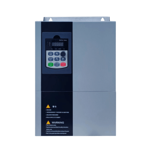
The VFD is the central component. It rectifies AC input power to DC, smooths it on a DC bus capacitor bank, and inverts it back to variable-frequency AC using IGBT switches and pulse-width modulation. For a detailed explanation of this process, see our guide on the VFD working principle.
Control mode selection depends on application requirements:
| Control Mode | Best For | Accuracy | Cost |
|---|---|---|---|
| V/f control | Pumps, fans, simple conveyors | ±2-3% speed | Lowest |
| Sensorless vector (SVC) | Conveyors, mixers, extruders | ±0.5% speed | Moderate |
| Flux vector (FVC) | High-precision winding, positioning | ±0.01% speed | Highest |
| Direct torque control (DTC) | Crane, hoist, high-dynamic loads | Very fast response | High |
Enclosure and environmental ratings are equally critical. IP20 drives belong in climate-controlled electrical rooms. IP54 or IP66 drives are required for dusty, wet, or washdown environments. For harsh environments like mining or steel mills, specify drives with IP54 or IP66 enclosures and enhanced thermal management.
Need help selecting the right control mode for your application? Our VFD for motor control guide breaks down speed, torque, and control mode selection in detail.
Not every AC motor is suitable for VFD operation. Standard motors designed for direct-on-line (DOL) starting may overheat when fed by a PWM waveform, especially at low speeds where the motor’s internal cooling fan is less effective.
Inverter-duty motors meet NEMA MG-1 Part 31 or IEC 60034-17 standards. They include:
For cable runs exceeding 50 meters, even inverter-duty motors may require shaft grounding rings or insulated bearings. High-frequency PWM switching creates common-mode voltages that induce shaft currents. Up to 20% of VFD-driven motors experience bearing damage if this is not addressed.
Power cables are the most frequently underspecified component in industrial VFD systems. Two types are required:
Input cables carry fixed-frequency power from the supply to the VFD. They must be sized for the VFD’s full-load input current, which is typically 5-10% higher than the motor’s rated current due to drive inefficiency.
Output cables carry PWM waveform power from the VFD to the motor. These are the critical ones. The fast-switching IGBTs in modern VFDs create high dV/dt (rate of voltage change) that interacts with cable capacitance and inductance. The results are:
| Cable Length | Risk Level | Recommended Action |
|---|---|---|
| 0-15 meters | Low | Shielded VFD cable, proper grounding |
| 15-50 meters | Moderate | Shielded VFD cable + output reactor |
| 50-100 meters | High | dV/dt filter or output reactor |
| 100+ meters | Very high | Sine-wave filter mandatory |
Always use shielded, three-conductor plus ground cable with symmetrical geometry for output runs. The shield must be continuous and grounded at the VFD end only (motor end floating) to prevent ground loops.
The input side of a VFD requires multiple layers of protection:
Circuit breaker or disconnect provides isolation for maintenance and short-circuit protection. Size the breaker at 1.25-1.5x the VFD’s input current rating. Use a Type B or Type C curve breaker. Magnetic-only breakers (motor circuit protectors) are preferred over thermal-magnetic breakers because the VFD already provides electronic motor overload protection.
Input reactor (line reactor) protects the VFD from power line transients and reduces harmonic current distortion. A 3% impedance input reactor typically reduces total harmonic distortion (THD) from 80-120% down to 30-40%. It also extends DC bus capacitor life by limiting inrush current and voltage spikes.
EMC filter suppresses conducted electromagnetic interference back onto the supply network. Required for compliance with IEC 61800-3 Category C2 or C3. Install the filter as close to the VFD as possible, with a dedicated low-impedance ground connection.
Surge protection device (SPD) guards against lightning-induced transients on the supply line. Critical for outdoor installations and regions with unstable grid quality.
Output filters protect the motor from the PWM waveform’s high-frequency components. Three types exist:
Output reactor (load reactor) is an inductor placed between the VFD and motor. It slows the dV/dt rise time from 5-10 kV/microsecond to under 500 V/microsecond. Use for cable runs of 15-50 meters. It also reduces motor audible noise caused by PWM carrier frequency.
dV/dt filter combines an inductor with a capacitor-resistor damping network. It further reduces the voltage rise time and limits peak voltage at the motor terminals. Use for cable runs of 50-100 meters or when motor insulation is marginal.
Sine-wave filter is a full LC filter that reconstructs a near-sinusoidal waveform from the PWM output. Use for cable runs exceeding 100 meters, retrofit applications with standard (non-inverter-duty) motors, or when multiple motors are connected in parallel from one VFD.
When Carlos, a system integrator in Sao Paulo, commissioned a 75 kW extruder drive with a 110-meter motor cable, he specified an inverter-duty motor but skipped the output filter. Within four months, the motor winding insulation broke down. The oscilloscope at the motor terminals showed 1,780V peaks on a 400V system — nearly 4.5x the nominal voltage. A sine-wave filter would have limited this to under 600V peak and saved the $8,000 motor replacement.
When a VFD decelerates a motor faster than the load’s natural coast-down rate, the motor acts as a generator. Excess energy flows back into the VFD’s DC bus, raising its voltage. Without a braking path, the VFD trips on overvoltage.
Dynamic braking is the most common solution. A braking chopper (transistor) inside the VFD switches excess DC bus energy into an external braking resistor, dissipating it as heat. Braking resistor sizing depends on:
| Application | Typical Duty Cycle | Resistor Sizing Approach |
|---|---|---|
| Centrifuge | 10-20% | Continuous-rated resistor |
| Crane hoist | 30-50% | Intermittent-duty, forced cooling |
| Conveyor emergency stop | <5% | Standard resistor, peak power rated |
| Winder/unwinder | 20-40% | Continuous-rated, thermal monitored |
Regenerative braking returns braking energy to the AC supply instead of dissipating it as heat. Regenerative units cost 3-5x more than resistor braking but recover 15-30% of braking energy. Economically justified for applications with frequent braking cycles such as cranes, hoists, and downhill conveyors.
Modern industrial VFD systems are not standalone devices. They are nodes in an automation network.
Analog I/O remains the most common interface:
Digital fieldbus protocols provide faster, more reliable communication:
For SCADA integration, map VFD parameters to the SCADA tag database. Typical monitored points include output frequency, output current, DC bus voltage, motor temperature (if available), and fault status. Control points include run/stop, speed setpoint, and torque limit.
Shandong Electric VFDs support Modbus as standard, with optional cards for Profibus, Profinet, and EtherNet/IP. This protocol flexibility allows integration into virtually any existing automation architecture without rewiring the control network.
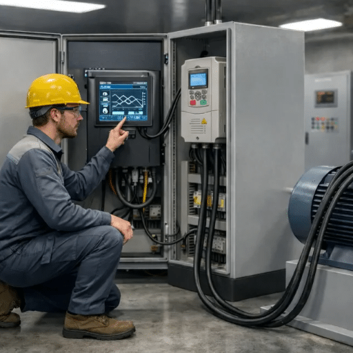
Grounding is the single most critical installation detail for reliable industrial VFD systems. Poor grounding causes EMI, random PLC faults, sensor noise, and communication errors.
Grounding rules:
Shielding rules:
Cable separation:
VFDs draw non-sinusoidal current from the supply, creating harmonic distortion. Unfiltered 6-pulse VFDs produce characteristic 5th, 7th, 11th, and 13th harmonic currents. Excessive harmonics cause:
| Mitigation Method | THD Reduction | Cost | Best For |
|---|---|---|---|
| 3% Input reactor | 30-40% THD | Low | Single drives, small systems |
| DC link choke | 25-35% THD | Low | Built into the drive, space-constrained |
| 12-pulse configuration | 10-15% THD | High | Large drives, critical installations |
| Active harmonic filter | <5% THD | Very high | Multi-drive systems, strict utility limits |
For compliance with IEEE 519 or IEC 61000-3-6, calculate the system’s expected harmonic injection and specify mitigation accordingly. As a rule of thumb, input reactors are the minimum standard for any industrial VFD system.
VFDs generate significant heat. A 98%-efficient 100 kW VFD still dissipates 2 kW of heat into the electrical room. Without adequate cooling, drive life expectancy drops by 50% for every 10°C above the rated ambient temperature.
Derating guidelines:
| Condition | Derating Factor | Action Required |
|---|---|---|
| Ambient >40°C | 1.5% per °C | Increase enclosure cooling, upsize drive |
| Altitude >1,000m | 1% per 100m | Derate the current or use a high-altitude-rated drive |
| Dusty environment | N/A | IP54 minimum, positive-pressure enclosure |
| Corrosive atmosphere | N/A | Coated PCBs, sealed enclosure, air filtration |
For high-power or space-constrained installations, water-cooled VFD systems eliminate the need for large ventilation systems and reduce audible noise by 15-20 dB compared to air-cooled equivalents.

Use this checklist for every industrial VFD system startup. Do not skip steps.
Even experienced engineers make these errors:
Using non-inverter-duty motors without output filtering. Standard motors overheat at low speeds and suffer insulation stress from PWM waveforms. If you must use a standard motor, install a sine-wave filter and maintain minimum speed above 30% of base frequency.
Ignoring cable length and dV/dt. Every meter of motor cable adds capacitance that interacts with the PWM switching. Above 50 meters, output filtering is not optional — it is mandatory for motor protection.
Poor grounding causing EMI issues. Grounding the motor cable shield at both ends creates a ground loop that injects noise into control circuits. Single-point shield grounding at the VFD eliminates this path.
Missing input protection. A VFD without an input reactor or disconnect is vulnerable to power line transients. One voltage spike from a nearby capacitor bank switching can destroy the rectifier bridge.
Wrong braking resistor sizing. Undersized resistors overheat and fail during aggressive deceleration. Oversized resistors waste money and panel space. Size for the application’s peak braking power and duty cycle.
Inadequate cooling. Installing a 200 kW drive in a small enclosure without ventilation guarantees thermal shutdown on hot summer days. Calculate heat dissipation and design cooling accordingly.
An industrial VFD system contains seven core components: the VFD itself, the motor, input and output power cables, input protection (breaker, reactor, filter), output filtering (reactor or filter), a braking system (resistor or regenerative unit), and control/communication interfaces (PLC I/O, fieldbus, HMI).
Standard VFD manufacturers recommend maximum motor cable lengths of 50-100 meters without output filtering. With an output reactor, this extends to 150 meters. With a dV/dt filter, 200-300 meters is possible. Sine-wave filters allow cable runs exceeding 500 meters. The limiting factor is voltage reflection at the motor terminals, not conductor resistance.
Yes. At minimum, a 3% input reactor is recommended for every industrial VFD installation. It protects the drive from line transients, reduces input current harmonics from 80-120% THD down to 30-40%, and extends DC bus capacitor life. For strict utility harmonic limits or multi-drive installations, add an active harmonic filter or use 12-pulse configurations.
dV/dt is the rate of voltage change produced by the VFD’s IGBT switching. Modern drives switch at 3-10 kV per microsecond. This fast edge interacts with cable capacitance to create voltage reflections at the motor. dV/dt filters slow this rise time to safe levels, protecting motor insulation and reducing bearing currents.
Use a dedicated PE busbar connected to the building’s main earth. Connect the VFD chassis, motor frame, and cable shields to this busbar with short, flat copper conductors. Ground output cable shields at the VFD end only. Maintain 300mm separation between power and control cables. Never daisy-chain ground connections.
Use shielded three-conductor plus ground cable specifically rated for VFD output. The cable must have symmetrical geometry, continuous metallic shield (copper braid or aluminum foil), and insulation rated for at least 1,000V peak. Standard motor cable is not suitable — the PVC insulation and lack of shielding make it vulnerable to capacitive charging currents and EMI.
Yes. VFDs accept analog speed references (0-10V or 4-20mA) and digital commands (run, stop, direction) from PLCs. For more complex control, use digital fieldbus protocols such as Modbus, Profibus, Profinet, or EtherNet/IP. These allow the PLC to read drive status, set parameters, and receive fault notifications over a single communication cable.
Industrial VFD systems are only as reliable as the components and installation practices built around the drive. The VFD itself is often the most robust component in the system. The failures that cost plants thousands in unplanned downtime usually come from peripheral oversights: a missing output reactor on a long cable run, a motor cable shield grounded at both ends, a braking resistor undersized for the inertia of the load, or an electrical room that turns into an oven every July afternoon.
Reliable industrial VFD systems require system-level thinking. Specify every component. Ground every shield. Cool every enclosure. Test every protection. The checklist in this guide gives you a framework for doing exactly that.
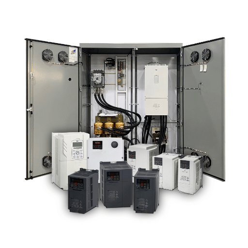
Once your system architecture is defined, the next step is selecting the individual components. Our step-by-step guide on how to select a VFD walks through voltage class, control mode, and load type matching. For application-specific system designs, contact our engineering team or browse our range of all-in-one cabinet solutions that integrate drive, protection, filtering, and cooling into a single shipped assembly.